Jan 14, 2021
Truss rod and Neck set work
Well, it’s been a long strange year, between hiding out on our mountain top and trying to avoid Covid as well as dealing with a loved one’s health issues. Instrument building was put on hold while I finished up work on my shop. Now that I’m beginning to get back to work on instruments, first up is building some jigs to not only restore a vintage parlor guitar, but also to use on the restoration of what I consider to be an historically significant Vega parlor guitar. The first task at hand was reinforcing the neck with a hollow square steel truss rod. Normally, the slot for the truss rod is done while the neck is still in the beginning stages of construction and it’s much easier to work with because it’s still mostly square. It’s considerably more difficult to do when the neck is already carved and it is being retrofitted. In this case, I built an open top box that not only holds the neck solidly but locates the fretboard surface directly under a plexiglass guide that the router can follows using a bearing guide. The bearing guide fits in the plexiglass slot and makes the whole process pretty unthunk. Here’s what the neck looks like when locked down in the jig and the next picture shows the neck with the truss rod epoxied into the neck.


August 16.2019
As I’d mentioned before, the Vega that I’m working on had fret slots that were no longer holding the frets in. The frets themselves were also no longer working after having seen some rather strange wear. So, the first job was to narrow the slots, To do that, I use some plastic slips that are just a few hundredths narrower than the fret tangs on the frets that are going to get installed. Those slips act as spacers after I’ve filled the fret slot with black epoxy. To keep the epoxy from going everywhere, I use some masking tape to cover most of the fretboard surface adjacent to the slots.
This shows the fret slots both before and after resizing. I still need to run the fret slot saw through those three newly sized slots but that won’t remove much material since the plastic spacers were already close to the correct width. Some of the old slots were close to the width they needed to be, like the slot immediately to the left of the middle position marker but others, like all those to the right of that slot, are far too wide and would never hold a fret. I like this approach as it keeps the original fretboard but also makes it able to be fretted in the usual manner.
And here’s a quick before and after comparison of how bad it was and it’s new and improved state.
While the frets have been filed to correct length and had the ends beveled, I still need to flat the frets with my straight edge sanding bar as well as recrown the frets. Following that, I’ll take a special file and “break” the edges of the newly cut bevels and then polish all the surfaces smooth and soft with some one thousand grit sand paper.
August 2, 2019
One of the main reasons I was given this Vega parlor guitar to repair had to do with some earlier repaired cracks in its lower left bout. It’s pretty easy to see the damage and the cosmetic appearance of the repair work it had had sometime earlier in its life.
There was a long crack in the side running parallel to the face as well as an area where it took a pretty serious bashing. One edge of the crack wasn’t aligned when it was glued up and so there was a ledge that ran proud of the surface the entire length of one side of the crack. The next shot shows the same area after I repaired the “repair.” Just for the record, the long black line that runs parallel to the face about a third of the side-width down from the top isn’t the repaired crack. It’s just a dark grain line that can now be seen after sanding the side out. The crack is now invisible with no offset in one edge from the other and the bashed in area is also now gone.
Normally, I would advise a client to leave an original finish alone, that it will impair the tone, regardless of how thin I’m able to apply the new finish, and, unless the finish is really bad, a refinish can take away a lot of character and originality, and in so doing, take away from the value of the instrument. In this case, my client wasn’t focused on resale value. However, he wanted a solid daily player and wanted it to look as good as it could look. The finish that was on the instrument was failing in places and was definitely obscuring the beauty of the Brazilian Rosewood. In addition, there had been enough obvious places where previous work done on the instrument took away from it’s originality that originality was really no longer a big concern. One thing is certain, when the lacquer is rubbed out, that rosewood is going to look glorious and with the subtle decorative touches on this instrument, it’s going to be one pretty little guitar again.
August 1, 2019
The frets on the old Vega guitar I’ve been working on have a wear pattern I’ve never seen before. While the outer ends of the frets have pulled free from the fret board and are sticking up , the middle section of all the frets are not just lower because of it. They actually show serious wear right down the center. I’ve got to wonder what the previous player was doing that would produce this kind of wear.
Once the frets were pulled, I double checked the neck angle and determined that it was still workable. It would require a custom bridge, but one that was still acceptable and would be more in keeping with the instrument than the Martin belly bridge that someone had used the last time the instrument was repaired. Before I could do that, however, the fretboard needed to have a concavity sanded out. I do that with a fairly heavy steel sanding bar made for just this kind of work. Both ends of the fret board were high so most of the wood was taken off the ends. Since the ends were actually thicker than the middle of the fretboard to start with, sanding it out actually made the fretboard look correct and even from the side when I’d finished.
July 30, 2019
This is going back a couple of weeks but I found it interesting so I’m going to post it even though it’s old and out of sequence. I’ve been working on a lovely little Vega parlor guitar that, while basically sound, still has a few issues. One of them, as I’ve mentioned before is the bridge plate. I’ve shown what the repair looked like from the outside but, since I have this fun little tool called an endoscope which I use to see inside an instrument body, I thought I’d show what the repair looks like from the inside. I often make some interesting discoveries, like labels pasted on the underside of a face, but in any case, I also often discover interesting constructional points. In this case, it was how the bridge plate repairs looked from the inside where the ball ends on strings contact the bridge plate. I wish I’d taken some before pictures just to show how much better things are now, but I didn’t. Even with a light on the end of the endoscope, these are still pretty dark.
The white disks are actually domed buttons made from the same maple as the rest of the bridge plate that exactly fit the recesses I cut in removing all the chewed up remains of that bridge plate.
This second shot shows the repair work done in the lower bout of the instrument. It had gotten banged at some point and one very long crack had been the result. Here’s a shot from the inside showing the previous repair person’s method and his lack of concern for cleaning up his work. Since it’s obvious that he didn’t remove the face or back to do this work, and the damage is at the lowest position on the lower right bout, I’m at a loss to how he was able to do this work. But, since he was able to scrape off an area to glue in new kerfing and cleaned up afterward, it doesn’t make sense that he left all the ooze out above the kerfing that came from the epoxy he used.
July 17, 2019
What follows are some shots of the mandolin I recently completed with it’s lacquer finish polished out.
Once the initial sanding is done, the rest of the work doesn’t really feel much like work at all and a great deal of it is done with machines. As I’ve mentioned before, getting a scratch free finish that looks almost wet is not really that hard to obtain if you have a proven method. Thanks to Bob Benedetto, I have just such a procedure. Bob makes some of the most highly regarded Jazz archtop guitars in the world and his approach is pretty straightforward, I won’t be letting slip any trade secrets and, as long as I use to struggle to get that glassy scratch free finish, I thought I’d go over it quickly for those who are challenged with this part of a build. Sometimes it seems like people present lacquer finishing as being one step removed from alchemy. First, after letting the sprayed instrument out gas for about a month, I sand it down flat. No shiny spots or other low spots is the goal. Once I’ve done that, I just keep working through the grits, alternating direction of sanding for each grit so I can tell when I’ve totally removed the previous grit’s scratches. Once I’ve reached 1000 grit I take the instrument to the buffing machine. I have two different grits of Menzerna polish that I load the buffs up with. There’s a third grit that’s a bit more aggresive in its cut but I find that it rounds things out to much. I can get crisper detail when I use sandpaper. Now here is the biggest trick to getting good results from the buffing machines. I cover the instrument in a very thin coat of mineral oil. That allows the grit on the buffs to do their work without heating up and dragging the finish. Once I’ve finished with the buffs, I use a random orbital handheld buffing machine used on car finishes with foam buffing pads attached. On them, I use a pair of 3M products called Perfect It and Finesse It. You don’t have to use much force or speed with these products and when you’ve used the finer compound, the results are fantastic. I don’t like to think about what I’d do if they stopped making those products.
July 16,2019
While I’ve been waiting for the lacquer to dry sufficiently on the mandolin I’ve been working on, I’ve started in on a new repair/restoration job on a beautiful old Brazilian Rosewood Vega guitar from the 1920’s. At some point in its life, it was damaged by heat and/or sever humidity change. The kinds of cracking in the sides and face point to that pretty clearly. Also, it appears that, when it came to me, it had already gone through three different bridges. In any case, the bridge that was on it was not period correct and, because of less than stellar repair work, the bridge patch was really chewed up. This shot of the area under the bridge looks worse than it actually is but it’s still pretty bad and I’ve had to mark on a separate piece of attached paper where the actual bridge pin holes will need to be drilled when these patches are in place.
Fortunately, I have a set of tools that address this problem very elegantly. One part of it cuts small hemispherical buttons out of a piece of wood similar to what the bridge patch is made from . There’s another tool that cuts a similar hemispherical round in the bridge patch. Here’s some of the tools I use to do this.
The piece of wood at the front is a piece of scrap that I used to make sure that the button would exactly fit the receiving cut out in the bridge patch.
I’d call that a pretty good fit. The hole in the center gets drilled away when the hole for the bridge pin is cut. Once again, I have to say, I love good tools.
July 14, 2019
I’m in the homeward stretch in completing this mandolin. At this point, with the finish on and “outgassing,” I have time to work on things that aren’t effected by the drying lacquer. In this case, I’m leveling and crowning the frets.
I start off leveling the frets using a rectangular steel bar that has had a flat machined into its surfaces. It’s heavy and dead flat and I know that I can depend on it to get the frets perfectly level as well. I ink up the tops of the frets with a Sharpie and then take the bar with a strip of 400 grit sandpaper double stick taped on to it, and sand until all the frets are shiny.
Once that’s done, I have to deal with having frets that now have a flat sanded into their tops. I do that with a tool called a crowning file. It’s a file that has a concavity that matches the original curve in the top of the frets. Once again, I break out the Sharpie and ink up the frets. When I’ve filled each fret so that I’ve reestablished the crown to the fret, I take increasingly finer grits of sandpaper and polish away and file marks. This part of the build, simple and straight forward as it is, is critical to the ease of the later set up. I take my time with this little procedure. It’s truly an investment in time.
May 14, 2019 Starting a Finish
I’ve finally come to one of the most rewarding parts of a build with this mandolin, namely, laying on a finish that shows off the beauty of the wood. My approach to finishing is decidedly old school. I spray my instruments with lacquer and there are quite a few reasons why I use it. First, with the gun dialed in, I’m able to lay down a coat far thinner and flatter than I ever could with a brush. Also, when one looks at longevity, it’s obvious that it is a finish that can stand up to decades of use. It’s easy to polish out to an unbelievable glassy clarity and it’s relatively easy to repair if it ever chips or is abraded off. But it does provide a few challenges.
While my studio is almost complete, I have not yet been able to build what will be my spray booth. At present, I am having to spray in a large enclosed area but one that is still somewhat dependent on the level of humidity in the air. If I spray when the humidity level is too high, I risk catching moisture under the finish which causes a finish problem known as blushing. It can be removed by spraying another chemical on top of it called lacquer reducer but it’s best just not to spray when you are likely to get it. On this mandolin, I thought I’d get a nice window of warm dry air but instead, we’ve been faced with rain for almost a week. I don’t know what happened to the summer we were enjoying but it’s pretty wet at present and it’s making me feel more driven than ever to get my booth built. At any rate, before the rains descended, I was able to get a wash coat and a couple of leveling coats on the instrument. Because I spray a colored lacquer on my mandolin’s, it requires that I first get a very flat finish. If I sprayed a coat of color without first getting a dead flat surface, when I later tried to sand the surface flat, I’d more than likely sand into the color layer which would result in an uneven color. So, I’ve learned to get a flat surface prior to spraying color. Here’s some very preliminary shots of this instrument in it’s first layers of clear coat.
One nice thing about the rain has been that it’s allowed me to slow down and really attend to the little details without feeling pushed by the time it takes. There are lots of places where seams join or inlays were inset where pin holes and fine lines have shown up and only after the first layer of lacquer has been sprayed. I’ve been doing what are called drop fills. They are, as the name implies, places where I drop very small amounts of lacquer to fill tiny voids. Spraying additional coats of lacquer alone will not get rid of those lines and pin holes. Surface tension prevents that and the voids just keep getting carried through to the surface of every subsequent sprayed layer. With my main concern being that I avoid any opportunities to sand through the color layer, the time to do this work is before the color is sprayed, not after.
To obtain that truly flat surface, the instrument has to be scuff sanded and wet sanded with each layer. However, before I did that, the latest coat of lacquer was given time to harden a bit. Rubbing out the lacquer requires using a very fine grit of sandpaper, lubricated with water and a drop of soap. If the lacquer hasn’t sufficiently dried, the sandpaper just loads up with sticky finish and can actually cause damage.
Today, I will wet sand the previous coat of clear and lay down one additional layer. Later today when it’s had a chance to level out and dry, if the surface is uniformly covered and with no surface flaws, I’ll spray all the maple and spruce portions of the instrument with a color coat. That requires that all the ebony parts of the instrument be masked as well as the abalone shell rosette. My tip of the day for anyone doing work like this, where you are attempting to section off an item for different colors of paint or lacquer is as follows. After spraying and before the lacquer or paint can dry, pull off the masking tape. If you try and remove it after the lacquer has dried, you’ll end up with what appears to be a torn edge where the tape separated from the finish. Not a good look. By pulling the masking tape off while the surface is still somewhat wet, you end up with a clean edge.
April 25 Inlays and Sanding
Over the course of the last month, I’ve had the lovely challenge of doing some new things when it came to decoration. It’s been a pretty focused process of trying, failing, retrying, and coming up with something that works. It’s been a slow but rewarding process, given the effort involved. I had two places to ornament left on this mandolin; the peghead and side markers. The side markers seemed almost dictated by the form the inlays on the face of the fretboard took. I simply made bars that fit between the frets at the various positions marker locations mirroring the widths of the fretboard inlays. I made them out of mother of pearl with tiny blue pua squares at the ends. The only difficulty with these involved working on related pieces that were that small. To make handling the little bits a bit more doable, I glued them on to a larger backing board and then, all together so that I could maintain even widths between the pieces.
The inlayed set ended up looking like this:
The peghead has been the greatest challenge of all as it combined working with inlayed wood, or marquetry, something I hadn’t done before, as well as working with plastic. I’d held off on using plastic, trying various other materials like solid and powdered Lapis Lazuli and reconstituted shell and stone. Nothing seemed to have the right color for the bluebird that had been requested. I finally found a piece of lucite that came about as close as I could find. One of the most enjoyable aspects of this inlay was learning from my client what the typical habitat was for this bird and recreating the Dogwood blossoms found on the trees it normally perched upon. They were made from some exceedingly figured and bright mother of pearl. Each has a center disk of gold leaf. I g a kick out of making those and trying to get a natural look rather than a stylized one.
The shot above shows the blossoms with the dot of glue covering the gold leaf before being sanded flat. Finally, the end result of a lot of routing, chiseling, and inlaying into an epoxy matrix looks like the following;
There are still a few finishing touches before I’ll call that peghead done. One thing I have to address is the birds beak. The width of the beak is so small that, if I don’t do something to lighten it up relative to the surrounding ebony, it may just get lost. I’m thinking a super thin piece of mother of pearl could work as a highlighting reflection line. However, I’m probably going to hit it with a test spray of lacquer to see if that makes it more present. I also still need to inlay the one talon that would show the birds orientation in this pose and I also need to add in the lines of the wing and tail feathers. That last part, more than anything else is, I think, really important as it clearly shows the position of the bird on the branch, looking back over it’s shoulder. Those lines will be put in immediately prior to, and then protected by the lacquer that will then be sprayed on. And while all that’s been going on, I’ve been slowly running through the grits getting it prepped for getting a finish. If asked what the most difficult aspect of this part of the build was, I’d have to say it was working with materials that were so very different in consistency. Cleanly capturing the stone-hard mother of pearl between the pieces of soft mahogany that made up the branches in a seamless way was quite the trick.
March 10, 2019 A detour into Aesthetics
As is often the case with instrument building, an order of operations needs to be followed or things get difficult. That is very much the case with attaching the frebtboard to the neck. Because hammering or pressing frets into that portion of the fretboard that isn’t supported by the neck is impossible after the fretboard has been glued to the neck, I have to deal with those frets first. However, before I can drive those frets in, I really have to first install the inlays. It’s much harder to clean up a fretboard after doing some inlay work if the frets are already in, so, inlays come first.
The inlays the client has requested for the fretboard are what are usually referred to as block inlays. To be honest, I’ve only done one block inlay design before and that was on a rather rare and expensive Gibson Southern Jumbo guitar. The blocks on that instrument are actually more like pairs of parallelograms, not squares but they still involve a lot of the same concerns and processes. In the case of the Gibson, my job was made much easier because I was able to purchase the inlays already cut to size, since that pattern is rather famous. Also, by having the size of the inlays dictated to me, figuring out how to locate them on the board was pretty obvious. I can’t say the same for this inlay job. This shot shows me sizing the highest position block inlay while cutting and attaching the pua shell strips.
A number of little aesthetic questions came up in the process of inlaying this mandolin. The first question, once answered, actually answered most of the rest and that one has to do with the height of the blocks. That might not seem like that big a questions but a number of problems are presented when determining the answer to that question. The first question has to do with how much of the ebony fretboard should show above and below the inlay? At the nut end of the board, that isn’t a hard thing to determine. It becomes a much bigger question when you look at the highest fret position which has a very narrow area in which to work. Once I was able to get proportions to work there, I could maintain those dimensions on the balance of the markers. I cut out numerous blocks in white paper to see which one provided enough of the ebony fretboard to show above and below the block to frame it. Another aesthetic question that came up with had to do with the super thin blue Pua strips that framed the white mother of pearl. Obviously, at no fret position, should the frame material look equal to that which was being framed. The mother of pearl had to be wider. Again, the narrowest fret position pretty much determined the sizes for the rest as it was the hardest one in which to fit everything in while keeping relationships looking good. It seems funny almost that all of those different requirements were in initially dictated by what was determined to be available from that highest fret position.
Having determined the relative dimensions of the ebony reveal or frame, the next major consideration was also already determined, namely the width of the Mother of pearl blocks as they stepped up or down in size dependent on their position on the neck. They needed to look like they were increasing or decreasing evenly. With the total height of each fret position space dictated by the fret dimensions, and the corresponding bit of ebony above and below the inlay, the various heights at different positions was pretty much dictated as well.
Finally, the question of width had to be addressed. Should the inlays extend beyond the outer strings on the base and treble sides, line up with the outer most strings, line up with the inner most strings of the outer most pairs of strings, or come up short? After looking at a lot of guitars and mandolins with block inlays, I decided upon this.
I’m really liking how those thin lines of Pua look with the mother of pearl. They somehow lighten the look of the large blocks and makes everything look more graceful.
Probably as hard as it was to determine the sizes that worked aesthetically, keeping things aligned while the inlays were gluing up was a challenge all by itself. The top and bottom edges of the inlays have to be run parallel to the frets that they are next to. With such small blocks, being off even by as little as one millimeter is noticeable. The trick here is to make the recess that was routed out for the inlay hold and locate the inlay correctly.
February 19,2019 Finishing Touches
I have to confess, the thing that first attracted me to this model of mandolin was not it’s beautiful, ringing tone, which it did indeed have. It was instead the instruments lines that first got my attention. I loved the Art Nouveau inspired sinuous curves of the body and the correspondingly curvy asymmetric scroll peghead. I also liked how the end of the fretboard was designed such that it echoed those body lines. However, in cutting the curve into the bottom portion of the fretboard, a problem comes up, the fret ends show while the rest of the frets are hidden inset inside the binding.
For that reason, I bend a trim piece and I prep the fretboard by letting the binding extend slightly beyond the end of the fret board. By capturing the end piece, it prevents an end catching on something. When the end piece is glued into place, things end up looking pretty clean and finished.
February 15, 2019 Compound Radii
I love simple, effective tools. Anything that gracefully allows me to do good work is welcome in my shop and studio. It’s especially appreciated if, in it’s simplicity, it is also inexpensive. I find a joke somewhere in all of that. I find it humorous that something that can be cobbled out of simple and inexpensive pieces of wood and metal can get the same results as an expensive CAD milling robot. However, running counter to my Geppetto nature is my appreciation for the tool to which I’m about to pay homage. I apologize for the rather busy background. Such is the current, rather disrupted nature of my tool room.
This machine is neither cheap nor simple. In fact, it looks like, after it’s finished doing it’s wood working chore, it could also vacuum the cat or perform any number of other impossibly involved and unpleasant tasks. However, this machine was built to do only one thing and that is to sand the surface of a fretboard. If I were only sanding my fretboards flat, I could do that easily with a simple flat sanding block. But I rarely sand boards flat. Presently, I’m sanding them to a compound radius or, if it’s easier to imagine, a conic section. For decades, I sanded a radius into fretboards using sanding blocks that had a concave surface milled into one side. The only form that can be produced with that kind of sanding block, in geometric terms, is a “Cylindrical section.” It worked all right but it had one issue that wasn’t really all that acceptable. The problem was, as the fretboard widened out, with the strings correspondingly splaying out to follow that increasing width, there was no way to maintain the slowly increasing string height equally over the entire length and width of the fretboard. This machine solves that problem and one other by swinging the fretboard over a sanding belt while attached to a pair of different length swing arms. This allows me to cut a perfectly smooth radius called a conic section into the board . Now, all the strings follow the radius at an equal height. Also, the action for all the strings, measured at any fret position, is also equal and proportional, while still taking into account the heights required for the different string gauges.
Finally, and this is admittedly pretty nit picky, the edge of the fretboard is a consistent width for its entire length. Getting the radius to transition smoothly while following the increasing width of the face of the board, yet simultaneously maintaining a consistent side width as well, is not something I think I could have ever learned to do by hand. Certainly not something that would be quick to do, even if I could figure out a way to do it by hand.
February 7, 2019 Cantilevered Support
This lumpacious looking block of wood is what will become a fretboard extension. It’s found on the Gibson F models supporting that portion of the fretboard that runs directly over the face, allowing more of the face to vibrate while still providing a flat, inflexible support for the fretboard. It was a step up from their A models where the fretboard was simply attached directly to the face. I’d call that an innovation as it improved upon the original design.
I like innovation if it is in response to improving something and not in just giving the builder ad copy. So, while my mandolins are heavily inspired by the Lyon and Healey mandolins of the past, they are not slavish copies. I’ve tried to use innovations that make sense and would likely have been something done in latter iterations of the model. Like the old A model Gibsons, the fretboards on the A model Lyon and Healey mandolins were attached directly to the face. While it’s meant more work for me, I think it’s an important enough innovation that I’ve included it on my instruments.
The first, most critical aspect of this block is that the grain is orientated to provide the majority of it’s strength such that the fretboard it supports remains flat over the body. That means that this piece has to have what would be called, “Vertical Grain.” If you put a stack of business cards together, all of them sitting on their edge, you’d have a good model for the grain direction of this block of wood.
Getting the grain orientation is critical but it’s very easy to accomplish. All one has to do is cut the block with that needed grain orientation in mind. The second aspect of this block that isn’t at all easy has to do with the fact that this part is what could be called a “Captured,” member, that is, it has to be made such that it fits perfectly between other pieces. In this case, the block has to act as an angled support that fits between the instrument’s face and its fretboard. It also matters that the surfaces meet very tightly for a number of reasons. First, the surface that fits under the fretboard has to be cut so that it perfectly matches the angle of the neck. If the fretboard surface is not correct, then there would be a pronounced hill or valley where the fretboard met the body. If the face bearing surface of the block didn’t fit tightly, the block would not have enough surface area for it to adhere to the face well enough to handle the torque the neck places on it. This is where handwork comes in. I start by making sure the block matches up tightly with the surface of the face. to do that, I use a lot of carbon paper. Once the block is correctly oriented, I pull a slip of carbon paper between the extension and the face and that gives me a very clear idea of where wood needs to be removed. Once the block fits tightly on the face, I extend lines along the edges of the neck onto the block and then plane down to them which gives me an unbroken angle for the fretboard to be glued upon. When it’s finished, it looks like this.
February 2, 2019 Light Necking
Given the fact that the neck and the fretboard are the conjoined parts of a stringed instrument where the majority of our physical interaction with the instrument occurs, I tend to tend to invest some pretty serious focus and attention to their construction. For me, the picky work begins by tapering the fretboard to the exact dimensions requested by my client. This particular fretboard is a bit wider than most but it should work well for my client as the dimensions were taken from an instrument he has and likes the feel of. After spending a lot of time making sure that I’ve hit those dimensions exactly, the next bit of work is to then change those dimensions to accommodate the ebony binding that’s going to be attached. This shot shows the fretboard cut to that reduced width. You can just make out a slightly darker area on the neck where the step will receive the binding.
Prior to gluing on the binding, I fill the fret slot ends with a tiny amount of modeling clay to prevent the glue from filling the slots. It’s a few minutes of time invested that saves me tons in not having to chip glue out of some very tight slots.
At this point, the binding strips are attached using binding tape. Since all that can be seen at this stage of work is the fretboard covered in tape, I’ll skip it and instead, show the specialized tool I use to clean the clay out of the fret slot ends. I sometimes find it hard to believe how such a simple purpose built tool can save so much time and effort. This shot also shows the ebony binding in place.
I bind my fretboards like this for a number of reasons, but there are two in particular that are at the head of the list. The first reason has to do with feel. I like the feel of polished ebony far more than the feel of plastic. Dense and free of the feel of grain, it really works well. The other reason has to do with appearance. Having the frets cut to fit in the closed end slots means that the fret ends are hidden from view. I used to just hammer them in with their ends exposed and then filled any gaps by melting in some lacquer stick, but they always ended up looking a bit rough and unfinished. My current approach looks clean and simple.
January 15, 2019
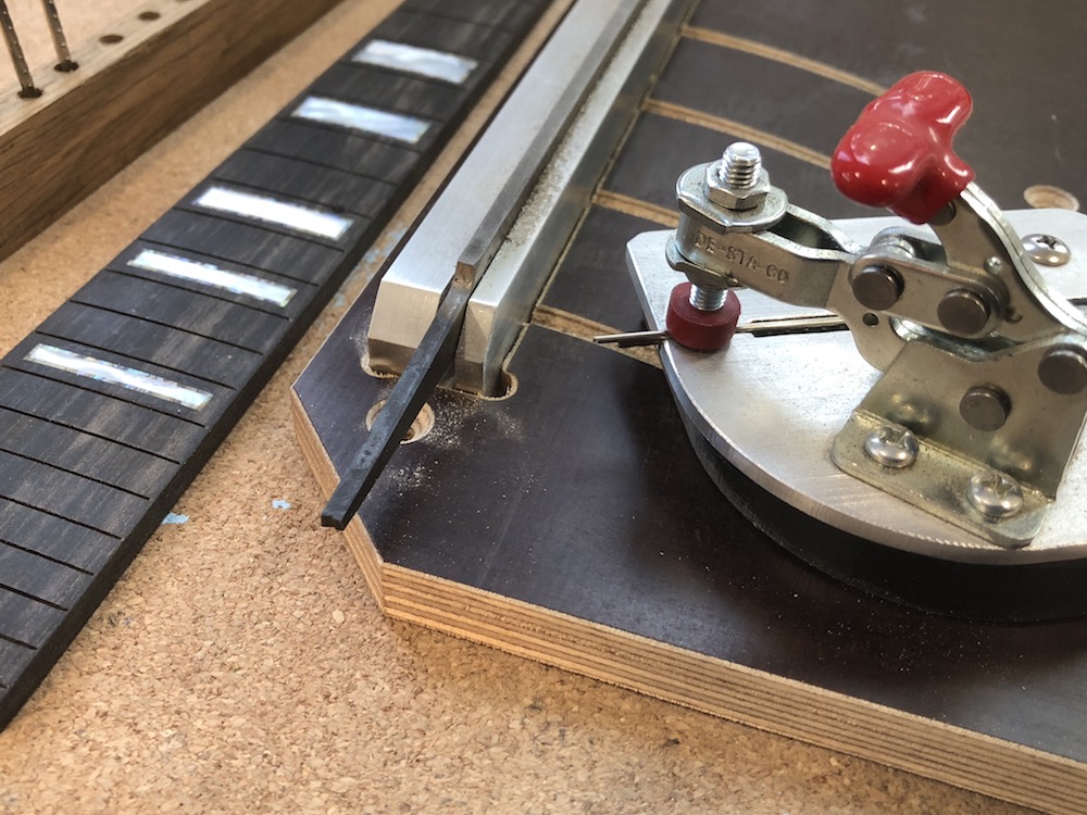
Almost as much as I love building instruments, I also love building tools and jigs. I especially like it when I build something that increases accuracy, speeds the process, or removes drama by removing some degree of danger or uncertainty. And it’s just the best when it can do all three. This is one that fits into that last category. This is a fret board slotting carriage.
Before I launch into the features of this jig, I should begin by saying that I choose to slot my own boards. I do that for two reasons. First, in building custom fit instruments, I sometimes find myself needing to cut non standard scale lengths. Second, when I’ve bought pre-slotted boards in the past, I have found that they are almost always mis-cut at one or more fret positions. So, I just cut my own, but I really don’t mind doing so with this jig.
Where the positions of the frets are determined is in the accuracy of where the fret slots are cut. One way to increase accuracy is to make sure there is no slop in the jig in terms of its movement past the saw blade. Straight forward and back is the order of business and zero side to side movement is the rule. This sled of sorts runs on two runners that slot into a pair of ways machined into the surface of the saw table. They run parallel to the saw blade and, with a jig that locates on two slots, the result is that there is zero movement in the jig other than the one I want. Not only does that make sure that the slots are cut in the correct locations, it also removes the problem of a widened slot caused by the jig moving from side to side as it is run past the saw.
Another aspect to this jig that increases accuracy is the manner in which the fretboard is clamped into position. There aren’t any clamps that screw down upon the work and could twist it out of position. Instead there are “fingers” that extend beyond the jig’s fence and press directly down on the fretboard, tightened down by inboard bolts and knobs. The twisting motion that’s done to tension them doesn’t transfer to the fretboard as a result. I’ve also set up the fence so that I can move the fingers to different locations That allows me to make sure that, no matter what part of the board I’m slotting, there are always two fingers providing clamping pressure. No chance of movement translates into a whole lot less drama as well.
Further accuracy comes from the fact that the fence is adjustable and can accommodate a tapered board if need be. the fact that it is adjustable also means that I can make sure that I’m cutting on a dead ninety to the center line of the fretboard.
Something that adds both accuracy and speed with this jig is that, where the fretboard lies, a saw kerf cut in the supporting table shows exactly where the cut will be. Aligning the layout marks I make on the fretboard with where the saw blade will actually cut is so easy with this jig it almost feels like I’m cheating.
Finally, and as a musician, most importantly, my hands never get anywhere near the saw blade and it’s whirling teeth of doom while using this jig.
It took an absurdly long time for me to get around to building this tool, but once I did, I was kicking myself for not getting around to it a lot earlier into my luthing career, I learned a hard little lesson on investing one’s time wisely with this one.
January 3, 2019 The Grace and Beauty of a Well Designed Tool
Here below is pictured the elusive peghead bushing reamer or bushing bit, in its native habitat along with a peghead that has just been machined using it. I’m not sure what kind of fetish it is but I have to be honest and admit that I love tools like this. It does what would otherwise be a difficult procedure and it does it quickly, accurately and cheaply. In this case, I have to drill holes just a tad wider than the holes I already drilled for the tuners to accept the tuners upper metal bushings and those holes have to be drilled in locations that are perfectly concentric to the holes I’ve already drilled. The bushings are installed as a press fit item and they provide a non wearing metal surface for the tuning pegs to bear upon rather than having to depend on the much softer wood of the peghead. There are two design features that really make this tool sing. First, the tip of the bit is a simple round shaft with no cutter. The size of that round tip matches the previously drilled holes and lets the bit stay centered on those holes as they are enlarged. No tricky measurements, no worries about if the bit is centered. The very design of the bit addresses those concerns rather gracefully. The second benefit of this tool’s design is the cutting flute. It is made like a mill rather than a drill and it cuts the ebony of this instruments peghead cleanly and with zero drama. These bushing holes don’t go all the way through the peghead but are only as deep as the bushings that will be fit to them. As easy as a tool like this makes doing a job that demands a high degree of accuracy, I can’t begin to say how much I appreciate its effective design.
January 1, 2019 One Argument for a Hand Built Instrument
The shot above shows how tuners should be set in a peghead. The pegs, held in strict distances from one another, fit the holes closely but without binding. The tuning buttons are offset from the sides of the peghead so that they can be comfortably adjusted and have bilateral symmetry relative to one another. Further, they are positioned so that the strings won’t foul one another as they run to the nut. It’s all very picky and precise work but it can be done and is done endlessly in factories all over the world. I’m going to try and outline what makes this work special and different from what comes from an instrument company and what makes a hand built instrument worth the bother. And that, in turn, should address why what was done with this instrument is rarely done in factory built instruments.
To explain my thinking on this, I have to go back a few dominoes. First, I have to admit that I’m kind of pushy when talking with a client about the desired physical qualities of their instrument to be. While how an instrument sounds is first and foremost on my list of what matters, a close second is how the instrument feels. It has to be shaped in a way that invites or, at it’s very worst, doesn’t get in the way. One of the key physical characteristic of the instrument that can really determine how inviting it is, is its width at the nut and the gradually increasing width of the tapered fretboard. As a musician, and perhaps because I’m only as accomplished as I am, I know that picking up someone else’s instrument can be downright frightening. If that instrument has a neck that is just a little different from what I like and am use to, I often find myself feeling like I’m having to fight the instrument to play cleanly. Further, I have a number of different guitars that, while minimally different in those proportions are, never the less, distinctly easier or harder to play. Obviously, to use an exceedingly overused phrase, size matters. And not only does size matter, but it matters down to the thirty second of an inch.
So I pester my clients. I ask them if they have an instrument or know of an instrument that just felt right in their hands. If they do, I ask them to either measure it at specific locations or take it to someone who can. With that dimension in hand, so to speak, I can then layout the neck and peghead accordingly. But that ability to build to variable sizes means that I am limited in my use of templates and jigs that would speed the process, as is the day in, day out method in factories. Instead, when I change the dimension of the neck at the nut, as needed by my client, it changes the layout of the peghead. That change is very small but that’s all it takes. Templates won’t work in that situation. If I didn’t take in to account the change of dimension into the width of the peghead, the pegs could be placed where the strings would foul one another or tuner buttons would be crowded by their closeness to the peghead. Again, that isn’t a problem for the factory as they’ve developed one set of dimensions that are known to work but it means that every instrument they build is to a fixed sized neck. It might be a neck that is built to a happy medium, quickly and efficiently, but it will always be to an average and may not feel as right as it could if they only they’d been built to fit the player. Having said all of that, one area that I think factories should incorporate into their products, is lines of similar instruments with gauged neck widths. Templates are going the way of the typewriter and are being replaced with CNC machines and those, unlike templates, can be easily directed to render objects with what ever dimensions you input.
Hand building allows me to hit the distances that matter on an instrument but, unlike with a CNC machine, it means I have to slowly and carefully layout a number of seemingly unrelated elements. There is a long list of critical measurements that have to be met in order for things to end up as they did in that first shot. This is what one of my pegheads looks like when I’m done laying out hole placement. I should also say that that micrometer caliper is no prop. It’s taken an embarrassingly long time to get to this point but one of the things that has sped things up considerably is the use of a dial caliper like this rather than a simple rule. While I don’t depend on it to set the distances between the posts or for keeping those posts in perfectly straight lines, it does help me quickly locate the pegs relative to the given dimensions of the peghead.
Next up, I spend a good deal of time drilling the top most tuner post hole for each set of tuners. Everything that follows keys onto the placement of those first two holes. I use a machined block of steel and a set of specially machined rods for help with the process. The holes in the block were drilled to the exact positions of the center points of standard mandolin tuning pegs and are arranged in a dead straight line. I pin the block to the back of the peghead through one of those first holes and use another pin to locate the lowest hole in the set. The pins have a pointed tip that is milled so that the it is located at the dead center of the pin. When I locate the drilled block, it’s pretty easy to hold the block just above the peghead and watch as the center point drops right on the center point I drew locating the bottom peg. The block is then clamped to the peghead and, using an electric hand drill, and guided by the holes in the steel block, I just begin drilling each of the holes. I pin each hole as I make them just to help keep things from moving.
Once the holes have been started, I take the peghead to the drill press and use those holes to register where the peghead gets clamped relative to the location of the drill bit in order to finish each of the holes. The result of all of this is clean, accurate work with the kind of tight tolerances shown in the first shot in this series.
Next up, a sighting of the rare and rarely seen tuner bushing bit!
December 28, 2018 The Joining
With the binding glued in place, some major cleaning up is in order. This is done mostly with scraper blades. I use those rather than sandpaper for a number of reasons. First, binding that’s done right is uniformly even along its length. It’s hard to maintain that even conformity with sandpaper. It tends to round things off, even with a sanding block, and this is one place where things have to look clean and crisp. Ths scraper blade can use the sides of the instrument as bearing surfaces and it makes keeping that uniformity fairly easy to maintain. Another reason I prefer scraper blades, aside from their speed, is that they don’t produce ebony dust which can get driven into the soft wood fibers of the spruce face by sandpaper. This shows how the instrument looks about midway through clean-up.
Once the binding has been cleaned up, the body is ready to have the neck attached. As the binding runs into the area in which the neck is attached, it’s important that the binding closely follows the thickness of the sides.
As soon as the neck is attached, it’s time to make a heel tab for the heel of the neck. This is done out of ebony as well. I used to build this model of mandolin with a heel tab extending up as part of the maple back and covering over the heel of the instrument. That’s how Gibson mandolins have dealt with that part of the instrument’s design from their inception. As that wasn’t in keeping with the original Lyon and Healey design, I’m now having the heel end in a decorative tab. I bring the piece of ebony down to almost finished size before gluing it in place, it being so much easier to shape and size when it’s not attached to the body. This shot shows it still a bit oversized and has more handwork left to do in it, but once this has been done, the fretboard extender and the fretboard gets attached to the neck and the instrument is, for all intents and purposes, done. While the fretboard has to be highly accurate, it is a pretty straight forward bit of construction and isn’t particularly demanding. The fretboard extender is a trifle more work in that, instead of simply being glued onto a flat like the fretboard, it has to be shaped to conform to the shape of the face right where the fretboard will get attached. I’ll go into that in my next post. The only things that remain after those two thing have been accomplished are the inlays which, on this instrument, are going to be pretty demanding. I have to say, I’m really looking forward to the inlays this instrument will be getting. Along with being a real challenge in terms of what the design demands, they should end up looking very period and in keeping with the design of the overall instrument.
December 11, 2018 Binding Bound
I have finally reached the penultimate point in this mandolin’s body build; attaching the ebony binding. I find it a bit amusing that the task the results in the instrument looking so clean, classy, and finished starts off looking so decidedly unlovely. In this shot, you can see my use of padded strips of cloth protecting the soft spruce edges of the routed face from being being dented when I pull the binding cord tight. To add to its questionable appearance is the addition of a wax paper cover taped over all as well as some of the smeared squeeze out of the black glue which is what gives rise to the use of the wax paper for protection. At this point, not a thing of beauty or a joy forever.
Binding is strange work. On the one hand, the glue in the binding channel is drying while I’m pulling the binding strip into its channel which demands that I work quickly. At the same time, I have to work slowly enough that I can make sure that the strip is well seated. It makes for a very odd balancing act, and the clock is ticking. That, along with having to glue one strip on at a time and then wait until the join is completely dry before I can add the next strip certainly slows the pace. This little bit of ornamental protection requires eight separate strips to be glued in place. All the pieces either butt up against one other or meet in a miter, as at the points. All of that means that, after each is glued in place, some very careful chisel work begins on the ends. To complicate matters, a number of those piece are what could be called captured, located as they are within other pieces that had been glued in earlier. With those, I cut one end to finish proportion and bind that end in place with my rope. That leaves the other to be moved in and out of position while I trim an end to final length so that the end fits tightly after the piece is in it’s final location. Those captured lengths are trixy.
Another important aspects of this job involves knowing where and when to put tension on the binding cord. Knowing that lets me seat the binding squarely in the channel. If there ‘is any skill involved in this little procedure, it’s in knowing where and how to put tension on the binding cord as it’s wound around the instrument. If you put tension in the wrong place at the wrong time, the binding can end up tilted outward, canted away from the sides and can end up looking pretty questionable. I’ve found that, if tension is put on the outside of the strip toward it’s narrow dimension by the binding cord, the pull will be towards the binding’s shortest length and will tend to pull it over and roll it slightly out of it’s channel, I’ve found that, if I pull the binding cord toward the middle of the side, putting tension on the strip in that direction, then “capturing” the binding with the rope and letting it pull the binding back into it’s channel, It’s like a little dance my hands do, as I work the cord around the body. Kind of fun, actually.
December 1, 2018 Decorative and Protective Embellishments continued…
I use a number of different adhesives in the construction of an instrument. I use hide glue for the center seam joins as well as for attaching braces to the face and back. I use it because it doesn’t tend to let go under heat or stress but, more importantly, it is transparent in it’s effect on the volume and tone of the instrument. For gluing in inlays, I use an industrial black super glue for it’s ability to wick into and fill very tiny voids. The one place I use epoxy is in attaching the body points. While they are very definitely decorative in nature, even more than the binding, they add a degree of protection in an area that is physically not very good at withstanding the daily knocks instruments experience. The epoxy is pretty good in its ability to hold on to smooth surfaces, like what you get with ebony, but it’s even better at remaining minimally flexible. For that reason, it is better able to withstand the sharp hit that that piece is often dealt. That hard, quick rap would pop off a point glued into place with a polyvinyl based adhesive in a flash. The epoxy gives just enough to keep that part in place. I would never, however, use epoxy any place where it would be exposed to tension over time. Epoxy joints deform over time under those conditions. For that reason, I could never use it in places like the neck or the join between side kerfing and the face or back. Knowing the various qualities of the glue I use has taken a long while to learn but it sure is handy.
Once the points have been attached, I can route the binding channel on the instrument. This is done using the same tool that I used for roughing out the shape of the face and back. It’s a modification of a tool usually referred to as an overhead pin router. My upgrade makes it possible for the router to rise and fall with the changing contours of a carved top instrument. I use a special plexiglass gauge that determines the depth and height of the cut it produces. Here’s what the instrument looks like after the initial channel is cut.
I still have to clean off the tops and bottoms of the two body points by hand. I have learned to limit my trust in routers to using them in areas where they are unlikely to cause chip out. The body points, as thin and unsupported as they are, are two areas that I choose to do by hand for that very reason. It’s a little slow but it’s a lot less scary to do because of that fact but also, my chisel doesn’t make the exceptionally loud noise that my router produces. I like getting things to the point where I can work them by hand.
Once the binding channels have been routed, it’ time to bend the ebony binding to fit. I am, however, getting a little ahead of myself. Before I can bend the binding, I first have to make binding that will indeed bend to the needed tight radii. I have had zero luck buying precut ebony binding, and I wouldn’t be surprised if I had the same problem with different flavors of wood binding as well, were I to buy some from the usual sources. The problem has always been that attention was apparently not given to the grain orientation prior to cutting. That has resulted in a lot of binding cut in such a way that it was almost certain to split when trying to be bent on the hot pipe. When looking at the broad side of a piece of binding, if the layers of wood are cut to run in planes parallel to that wide side, kind of like if you looked at the cover of a book and thought of the grain lines as if they were the pages of that book, it isn’t going to want to take a bend. If, on the other hand, it’s cut so that grain stacks up like the layers of a cake as you look at the wide side of the stick, it takes a bend as sweetly as you could ever ask. The major suppliers, for some reason, don’t seem to pay attention to that orientation and I’ve produced a lot of very expensive kindling until I realized, it wasn’t my ineptitude at bending that was at fault but some badly cut wood. Now days, I cut my own from a large and very expensive billet of ebony. However, if you use ebony much in your binding, that initial expense in buying one large billet becomes quite a savings, not to mention makes the work a whole lot less frustrating. In this shot can be seen my usual tools of the trade; an electric hot pipe, a stainless steel bending strap laying on top of the tray holding the water I wet the wood with, and a pair of fret nippers to cut the binding to rough length. Once the binding is glued into place and sanded down to final dimensions, the body is complete and ready to be joined to the neck.
Nov. 24, 2018 Decorative and Protective Embellishments
At this point in a mandolin build, where the final stages of construction take place, much of the work is focused on small details. One of those involves that place on the base of the instrument where the two sides join and the end pin is located and which enjoys the particularly unlovely name of the butt seam. When fitted with a decorative piece of wood, it’s also called the tail graft and I think I’ll go with that. When the sides made out of wood that is as white as maple, no amount of planing will prevent an obvious join. This join is traditionally dealt with (dare I say, “Covered up?”) by cutting and fitting an insert made from some contrasting colored wood. Often, that piece of wood is gently wedge shaped. While that wedge shape makes the design geometry a little more graceful and interesting, I think it’s true shape has more to do with allowing quick and very tight tolerances to be met in a place where gaps would really stand out. The beauty of a wedge shape is, if you make the wedge over long to begin with, you can take multiple passes on one edge until everything fits tightly. With a rectangular shape, once you go past tight, there’s no going back. With a wedge shape, if you are slightly off the mark, you can just take a couple of corrective passes with a well set up block plane and simply slide the wedge a bit further in. However, before I work on the wedge, I have to cut the wedge shaped recess in the mandolin. I knocked this little jig out many years ago. It works with both mandolins and guitars and, while it isn’t particularly lovely, it works so well, I’m hesitant to make its Mark II model.
The router has a guide bushing mounted to its base and that bushing bears against the inner surfaces of the jig legs that straddle the area to be routed. The only super critical issue to address in all of this, other than the original layout lines, is making sure the bit is centered in the guide bushing. If it isn’t, the edges of the cut, as measured from the center-line of the instrument, won’t be symmetrical.
When the needed area is routed out, the next step is fitting the wedge. The one pictured here is over long. You really don’t need to make the wedge more than a quarter of an inch beyond either end for fitting. I just got lazy and decided it was easier to make two cuts rather than four.
Once the wedge has been fitted tightly to the recess, it’s time to clean it up. I do that using a very fine set block plane. I’d like to take a moment here and sing the praises of good tools. If you are a wood worker, my best advice would be to think about what ever tool you use the most, or would like to use the most, and buy the best one you can afford. Think of it as an investment, if that’s what it takes to give yourself permission to spend as much as a really good tool costs. I love this little plane. It’s made from brass and it has real presence in the hand. Also, it’s heft, when set into motion, helps power the little gem through some pretty dense and highly figured wood. Also, it provides me so much feedback and is so easy to control, that I can do delicate hand work really quickly.
After the plane comes some fine sanding and then we are ready to move on to the body points.
The body points are more than just decorative. Those points are thin and would be easy to damage. Moreover, I try and learn from the things that work and don’t work on the instruments I am taking inspiration from. I’ve looked at quite a few old Lyon and Healey mandolins. Their body points came together like the violin the model took design cue from. Unfortunately, this is often an area where I’ve seen damage with the two separate pieces opening up at that very sharp edge. For that reason, this is one area where I employ a material to cap the point, like the Gibsons of the period had. However, unlike the old Gibsons, with their imitation ivory points, I use ebony. While I like the reproduction ivoroid binding that’s now available, for the most part, I like to limit the use of plastic on an instrument. Also, the binding on this instrument is going to be ebony and having all the various “appointments” made from the same material adds to a feeling of the instrument being true to itself and looking tied together. This shows the blocks as they are first glued on. Most of that will be removed in final shaping.
Nov. 15, 2018 Neck work, Go-Bar decks and paper ephemera folderol
It’s pretty amazing how the pace of construction on a mandolin picks up once the critical dovetail joint is finished. Immediately after refining that joint, it was time to make the peghead head plate or, if that’s not a familiar term, the peghead overlay. In either case, what I’m referring to is the fairly thick plate of ebony that is glued on to the front of the peghead. That plate does a couple of things. First, it’s a nice decorative element, but more importantly, it adds a tremendous amount of strength to a weak area of the neck. The peghead was formed by being cut at an angle and then reglued with the offcut flipped over and scarf joined to the back of the neck. That alone makes that weak area quite a bit stronger than the more typical way of forming the peghead, which is to simply cut out the side profile from a thick block of wood. However, as I’ve mentioned before, doing it that way relies on the limited strength of extremely short grain in the very area that is the thinnest and needs the most strength. So, by starting with a scarf joint, spreading out the cut and employing long grain fibers for support and then reinforcing that cut with a nice thick piece of ebony leaves me feeling very confident that this area is now seriously strong. As this next shot shows, it takes a lot of clamps to glue the headplate on.
Once the headplate is glued on, the fun part of cutting out the shape of the peghead begins. I start that procedure using the bandsaw and a jig that holds the neck in a position where its fretboard surface is parallel to the saw table. I do that because it results in a “swept back” appearance to the peghead. Here’s the jig I use to rough out the peghead.
Once the peghead has been roughed out, it’s time for some refinement. From the bandsaw, the peghead heads over to the drill press where a small drum sander has been chucked into the quill. With the neck still mounted in the jig I used with the bandsaw, I get ever closer to the final shape. At some point, I move away from the machines and start in on handwork. It would be slow work from this point on if it weren’t for the fact that the machines have already removed ninety five percent of the wood that was not part of the final shape.
Since working on the peghead doesn’t involve the body of the mandolin and since I no longer need the added access to the dovetail joint in fitting the neck, I’m finally able to join the back to the instrument body. I do that with a tool that I’ve grown to love over the years. It’s called a Go-Bar deck. The part of the instrument being worked upon is placed on a surface that has another surface held directly above it. Fiberglass rods are “sprung” by wedging them between the work on the bottom surface and the upper surface. This may seem like a rather primitive set up but it’s actually quite elegant. I can get things “clamped up” in far less time than by using actual clamps and the amount of gluing pressure is easily felt and adjusted by how stressed the rods are and where they are placed. Gluing the back onto the face and rim in this manner also gives me access to the soundhole through which I can clean out any excess glue from the kerfing. I also just like the way it looks.
Of course, before I could close up the box, as it’s called, I had to glue in my maker’s label. Now that might sound like a quick and easy thing to do, and it usually is, but not this time. Having moved to a different state since my last labels were produced, much of the information on the old labels was no longer accurate. While inputting the correct information on the label provided no challenge, printing it on paper so that the ink doesn’t fade and the paper it’s printed on doesn’t degrade over time does. It requires archival paper and ink, two things which are not in ready supply for me living out in the sticks as I do. Archival paper is relatively easy to find. Legal documents often require it, but archival inks are not easy to find and require a printer that takes them. So, for want of a label, I purchased a new printer with the ability to use archival inks. It’s something I imagine most people wouldn’t think would be a challenge in building an instrument but, seeing as how I want my maker’s label to last as long as I’ve built this instrument to last, it matters.
Oct 31, 2018 Construction of a Dovetail and other neck details.
I truly believe that the mandolin neck dovetail has to be one of the hardest joints in woodworking to produce. Technically, I guess this old school joint could be described as a sliding tapered dovetail with a conic section bearing surface. It’s so difficult, I finish the majority of the work on the dovetail joint before I invest in much work on the rest of the neck. While having to start over rarely happens, this joint is still enough of a challenge in doing really right, that it doesn’t make sense to do a lot of the additional machining until I know it will work. I also wait on cutting some of the finish dimension on the neck because I need some of the flat surfaces for reference surfaces when making subsequent cuts. I only remove enough wood so that I can fit the dovetail. “Fitting it” means more than just that the joint is a tight and stable. It has to result in the center of the neck lining up with the center line of the body. It also means that the angle of the fretboard surface, relative to the plane of the face, is set such that the strings will run over the bridge at a specific height. While bridges are often adjustable and could compensate for being off a degree or two with this angle, there is still an optimum height and resulting down pressure. Finally, the joint also has to end up with the fretboard surface co-planar to the face. In other words, the neck can’t be twisted off of center. This first photo shows how this joint looks at the end of the fitting process when things are tight. Obviously, there’s plenty of refining to do in shaping the heel and the neck shaft but at this point, the hard work, or maybe I should say, the demanding work is done.
Getting things to this point has involved well sharpened chisels, a douzuki saw, and small slips of sandpaper. Following the transfer of some very carefully laid out dimensions, I’m ready to cut away most of the waste wood with a very sharp hardwood dozuki. Once that’s done, the really tricky bit of business presents itself, carving that part of the neck that follows the curve of the rim. To carve the inside curves of that portion of the neck means carving into end grain. Genuinely not fun. This is one spot where nothing short of surgically sharp tools will do. After I’ve removed as much wood as I can with the chisels, I install the neck and begin pulling strips of sandpaper through the joint until it exactly conforms to the curved surfaces of the rim. The entire time I’m bringing the joint to it’s finished state, I’m continuously checking, with a number of different rules ,the orientation and alignment of the neck.
Once everything fits tight and is positioned correctly, I can move on to the balance of the neck. One of the nicest things about getting to this point in the build is knowing that a tremendous amount of the work that follows is going to be quickly accomplished by a few trips to the machine room.
I begin the machine room work by thinning the peghead. It’ll be getting an ebony cap that’s rather thick and, for the tuners to fit correctly, the peghead has to be thinned a bit. I do that on the bandsaw. I use the peghead’s face as my reference surface.
Using the uncut sides of the neck as reference surfaces, the next bit of business involves routing the neck to accept the hollow steel reinforcement rod I use. I don’t have a lot of faith in adjustable rods. I’ve seen too many rods that have ended up nonfunctional because of a broken nut buried in the neck. Also, with such a short length of tube, stiffness is not a concern. I trust in the fact that, for more than half a century, this kind of rod was used in Martin guitars. It is, to say the least, time tested and an even better application in a mandolin than a guitar.
I cut this channel with a router table, bringing the channel to its final depth by taking successively deeper cuts. Once the channel is cut, the rod is glued in place with epoxy and a strip of maple.
Once the neck has been tapered, I glue on the “ears” of the peghead. I usually use off-cuts from another part of the neck so that the color and chatoyance of the different parts match. The final challenge is positioning the small blocks so as to get the best match for flame. The match really only applies to the back of the peghead since the face is going to be covered with a headplate of ebony.
Oct. 7, 2018 Tweaking
No, not that kind. The kind of tweaking I’m referring to has to do with the process of making small adjustments on something. In this case, I’m tweaking how the neck joins the body. Over the years, I’ve built this instrument to the two different scale lengths in which the original was offered. The earlier scale was a longer scale of 13 7/8″. The Lyon and Healey company later shortened the scale to 13″. I have my hunches about why they did it but, in my case, I didn’t like the break angle I was getting with the bridge placement on the longer scale length instruments, so I felt like a small redesign was called for. Also, I had lucked into some really nice old company ad copy that focused on the construction of the neck but also did a nice job showing the angles of the dovetail joint. While the original mandolin has a few questionable design choices, how the body points were built comes to mind, the neck joint of the instruments I’ve looked at were always pretty tight. I think part of that is the narrower dovetail and so I wanted to make that change as well. Of course, as interrelated as the various parts and dimensions are with this joint, I have had to do some pretty serious layout work as well as to do a mock up with a sacrificial block. I’m liking how this latest tweak has the bridge sitting more in the center of the domed face and not, as it’s been in previous long scale instruments, sitting more on that portion of the face where the surface is just beginning to curve down to the tailpiece. The new position also works better with where the bridge sits relative to the tone bars in the instrument. This first shot shows the quality of the neck joint with the mock up neck. It’s tight, in line with the center line of the instrument and sitting at just the right height off the face of the instrument. But the most important measurement that this mock up proved was that, with these dimensions to the tail cut, the neck is set at the angle needed for the strings to hit the top edge of the bridge at the correct height. Even being off by as little as two degrees can result in major problems down the road. As the only thing this mock up was designed to check was the “tail” position of the dovetail, what would be the heel of the neck was cut away. On the actual neck, the sides will continue and meet with the body.
With the joint now tight and correct, I just transferred the dimensions of the working mock up to the actual neck and made the first two cuts. I don’t do those cuts freehand. Instead, I clamp a block onto the surface of the heel that was shaped with the same angled router bit that cut the receiving slot in the body, and I use it to guide my cut with a very sharp hardwood dozuki saw. I could go on for ever about how much I love those Japanese saws, they are just so logical and work so perfectly at doing really fine work but I’ll let the following picture demonstrate how well they can follow layout lines.
September 24, 2018 Heavy Necking
In building a mandolin, I feel like I’m bringing two very different approaches to woodworking together in the construction of one object. The body for this mandolin is defined by it’s smooth curves and was accomplished mostly by hand. While machine tools did play a part, they were usually used to get rid of a lot of waste wood in a very controlled manner so that it would be easier to accurately do the hand work that followed. The final surfaces were refined by using a low raking light and scraper blades. On the other hand, the neck of the instrument is mostly the product of my use of machine tools and involves a lot of straight lines and flat surfaces. I find the distinct differences in ways of working wood to be interesting and rather unique in building a carved top instrument. Certainly building a “flat top” guitar feels far different than building a carved top mandolin.
Constructing the neck all begins with the recognition that the flat plane of the fret board and how it relates to the body is all and everything. The instrument won’t intonate correctly if that plane is not perfectly flat. The instrument will be uncomfortable to play if neck lines aren’t exact. Also, because every other critical dimension of the neck works off that surface and won’t be right if it is not square or parallel to it, the surface of the fretboard becomes the reference by which all other dimensions of the neck are determined. Hopefully, as I work my way through this photo montage, what I’m talking about will become clear.
The first thing I do is to take the single neck billet, a rather thick but short rectangular block and make two raw necks from it. Making two from one isn’t about economy, although it is nice getting two necks out of a block of expensive vertical grain maple that was intended to make one. The real reason I do this comes a couple steps down the line and involves how the headstock is built. I’ve repaired enough instruments over the years to know that one of the weakest areas on an instrument is where the neck angles back to form the peghead or headstock. A luthier friend of mine who does mostly repair work actually has a little wall display of pegheads that have broken off their necks. The fact that that area is made up of a narrow piece of wood doesn’t help. It further doesn’t help that, if you just cut the headstock out of the thick block, the area of wood right where it angles away from the plane of the fretboard is made up mostly of short grain wood, which of course further weakens that area. Add to that the hundreds of pounds of pull acting against that peghead with the strings at full tension, and the deck gets really stacked in favor of failure. And finally, the fact is, people often lean or prop up their instruments in a way that makes them want to fall over, and with the peghead stuck out at the far end of what could kind of act as an Atl Atl, that peghead can pick up some serious speed before slamming into the floor. All of this makes for a real recipe for destruction, or, as luthier’s call it, “Job security!”
In order to build in some strength and to add greatly to the time and effort it takes to build a neck, I cut the raw stock into what you see here.
Bandsawing the billet into these parts gives me two necks, complete with heels as well as a color and grain matched “off cut” from the center that will end up glued onto the peghead as “ears” where the shape of the peghead is at its widest.
I like to honor Mr. Zorsi’s original design by gluing a black centerline down the length of the neck. However, instead of using the same material as was originally used, I make that decorative line out of Ebony. A number of years ago I bought a number of preslotted fretboards only to discover that the slots had been cut inaccurately. While I couldn’t use them as fretboards, they could be recut to make up some decorative strips.
This next shot show the glued up neck block.
This is probably a good time to talk about the machines I use and their set up. First, I should point out that making the actual cut is simple and quick. Through the use of clamps, jigs, and my favorite shop “tool,” industrial grade double stick tape, the work is held in very controlled positions and run through the machine with dependable results. Easy peasy. Not so easy is getting the machines and jigs set up so that they are cutting dead straight and accurate. That takes some serious time. I’ve already covered how I accomplish that set up in an earlier post but getting that right makes every subsequent step in the process possible. For instance, if the sides of the neck billet weren’t cut at a precise ninety degrees from the fret board surface, then that decorative center line would end up being in the wrong place for another operation that comes down the line. If that center line of Ebony weren’t cut so that its large flat surfaces weren’t perfectly parallel, when I glued the different parts up, the flat plane of the fretboard surface would no longer be flat. Also, in a latter step, the center line wouldn’t match up with itself. The place on the neck where it angles back to form the peghead also has to be cut dead accurately or the nut wouldn’t sit at a ninety degree angle to the center line of the neck and body. Being “out” on any cut just compounds the errors down the line. However, having taken the necessary time up front dialing the machines in makes the work go much easier.
When I reach this point in the necks construction, I use a method more frequently seen in high end guitar builds. I cut the neck at a diagonal and the offcut gets flipped around and glued to the back of the neck to form the peghead. This gives that critically weak neck area some much needed strength in the form of long wood fibers right at the angle. Here again, if the two maple pieces were not cut to be mirror images of each other, in terms of width, that centerline would take a jog when it was glued up and things wouldn’t line up. Again, most of this accuracy is imparted, not by my hand skills, although I do use a jointer plane at one point in the process. It’s imparted by well set up machines. Here’s how this type of pehghead set up works. First, the diagonal cut is made on a special jig I built.
Next, the offcut is flipped around to be glued on the back of the neck.
In the next couple of days, I’ll show how the neck is further profiled and the all important dovetail is cut into the heel.
September 8, 2018 Cutting the dovetail
And thus begins what I believe to be one of woodworking’s most difficult bits of joinery, the sliding dovetail joint on a mandolin. Cutting a dovetail is a hard enough joint in any kind of woodworking, but it’s another level of difficulty cutting a sliding, tapered dovetail, and when it’s done in a mandolin, it is especially hard. In fact, it’s my belief that it is such a challenging bit of work, that it gave rise to the use of what has become known as a sunburst finish. Along with sunbursts ringing the face and back of an instrument with increasingly dark dyes as you move to the edges of the instrument, it is also applied quite dark at the neck to body joint. I don’t think that was done for aesthetic reasons. I think that this is such a difficult joint to pull off perfectly, with no obvious joints showing, builders would often resort to filling any painfully obvious gaps with some form of wood dough. The dark stain would then cover the less then perfect work. I take more than a little pride in pulling this off with zero wood dough and I only rarely use sunburst finishes, knowing why they were used back in the day.
Layout on the instrument is how I begin to make this joint. It’s strange to think about, but the attitude a plane can take while flying kind of works as a good analogy for what I’m dealing with when laying out and cutting this joint. Given the three dimensions that a neck can move in, relative to the body of an instrument, its position can be looked at in the aviation terms of yaw, pitch, and roll. In the mandolin’s casse, the yaw refers to how the neck moves to the left or right of the instrument’s body centerline. In a mandolin’s case, you want zero yaw or your bridge will have to shift to the right or left of the centerline on the face to compensate. To be avoided. Pitch is also critical in that it defines how tipped back the neck is to the flat plane of the face of the instrument. Too little pitch and the strings will be painfully high off the fretboard or will require a very low bridge, resulting in a very shallow break angle over the bridge and very little down pressure “loading” the face which results in a loss of tone and volume. Finally, in this case, roll refers to how twisted the fretboard side of the neck is relative to the flat plane of the face. Exactitude with all three of these attitudinal concerns makes for one level of challenge. Things get infinitely more difficult when cutting the mating joint in the heel of the neck. In that case, not only does the “tail” of the dovetail have to fit the tapered slot in the body, the sides of the neck must also perfectly match with the curving sides of the upper portion of the body in what can only be described as a conic section. On top of that, the neck’s dovetail has to have the the taper cut so that, once the neck is installed, it will slide home in such a way as to leave enough of the neck proud of the face surface to establish the right bridge break angle. Challenges aplenty! Here’s a shot of the layout lines for the joint to be cut.
This next picture shows the mandolin body in my dovetail jig, held firmly in place with a multitude of clamps. A plethora, even! While this jig does speed the process up and gives me perfectly cut joints, getting the mandolin positioned exactly where it needs to be takes a good deal of time and a lot of dial caliper use. This step took a bit longer than usual as I rebuilt the plexiglass template that the jig uses. In doing further research on the original Lyon and Healy model, I discovered some old PR material from the factory that showed that my old template had the dovetail opening up wider than the original. I have found that, as I’ve been building my “Dream Shop,” the same attitude of “do-it-right” has resulted in my tweaking a number of my jigs and fixtures. The results of that have been good and many but, have been it has certainly slowed things down a bit.
This shot shows me wasting wood in the joint recess with a straight bit. I have to do it this way because, when I use the actual dovetail bit, I have to make the cut in one pass. I can’t do it in successive deeper passes because it would result in a joint with stair step sides. If I didn’t remove a lot of the wood previous to the actual finish cut, the mass of wood could cause the dovetail bit to grab resulting in the instrument possibly moving around in the jig. Not exactly a road to accuracy. So, I use a straight bit and make successively deeper cuts clearing out the waste wood. That’s followed by a dovetail bit with a bearing that follows the sides of the template.
Here’s the joint in all its finished glory. It always feels like a major hurdle cleared cleanly when this joint is done. Also, it looks like the back has already been glued on to the sides but it’s actually put in place temporarily just to see how things line up.
September 7, 2018 The Box Takes Shape
For me, this is the point in a build where things get exciting. With both face and back plates carved to finish dimension, and sides blocked and kerfed, it’s time to join all the players and get a mandolin body. It also helps that it happens relatively quickly when compared to how long the face and back took to carve.
There is definitely an order of operations in this process. The face gets attached to the sides first. The simple reason for that is that the dovetail joint in the headblock has to be cut before the back is glued on. Also, being the nit picky sod that I am, I also glue the face on in a way that gives me access to the inside of the instrument because it easily wllows me to remove any excess glue that squeezes out from under the kerfing. Given that, short of using a dental mirror, there’s no way to see any squeeze out that occurs should give everyone at least one reason to be impressed with my wife. She somehow manages to put up with the unfortunate fact that my retentiveness likely occurs in places other than in my luthing and probably also has played a major reason in why my shop is taking so blasted long to finish. Who else would build rough framing to the sixty fourth of an inch? But I digress.
This picture shows the face being glued on to the sides using a brilliantly simple but effective device known as a Go-Bar deck. Flexible rods are lodged between whatever is being glued up on the deck’s table with its upper surface. I use fiberglass rods that were purpose built for this application and they work perfectly. The amount of “clamping” pressure is easy to dial in simply by raising or lowering the platform upon which the work sits. Putting all those go-bars in place, while considerably faster than screwing multiple clamps in place, is still too slow for the glue I’m using. For that reason, while I’m putting in some of the key bars, like on the head and tail block, I set heavy iron weights on portions of the body until I can get to them with the go bars. It’s takes a bit of choreography but the result is a dance that is both very precise and very short.
August 28, 2018 Bring the Bling
For the last couple of days, I’ve been working on adding one of my “Maker’s Marks” to the mandolin I’ve been focused upon. For those unfamiliar to the phrase, a maker’s marks refers to those noticeable design features that distinguish one maker’s work from another. Most often, the two places where that usually occurs is the headstock or peg head of the instrument and its soundhole rosette.
On the peg head, there are often several different features that define that instrument’s maker’s mark. The logo is one and the shape of the peghead is the other. I guess it’s an old world version of branding, but it’s been with us for centuries. For example, for those in the know, a Stradivarius violin can be recognized simply by the shape and proportion of the scroll of the peg box.
When it comes to the maker’s mark on a soundhole rosette, depending on the instrument, many options are available. With abalone and mother of pearl often used to ring the soundhole, when wood marquetry is inlayed into wood, it’s different enough that it stands out and serves as a maker’s mark. When using the more typical materials, how they are arranged becomes the point of distinction. For almost twenty years now, I’ve been using an arrangement of mother of pearl and abalone that serves as one of my maker’s marks and it’s one I have to say, I really like the look of, Simply put, it has a center ring of very busy abalone framed on both the inside and outside with thinner lines of mother of pearl. Now, I’ve seen pre world war I Martin guitars that have a large inside ring of abalone bound by ivory, but none that use mother of pearl in a consistent manner. So, I think I’ve come to claim it as a maker’s mark. Certainly none of the other current builders use it.
I should make the point here that, my maker’s mark, while impressively flashy, is a pretty easy bit of work for a guitar. Nothing could be further from that than that same rosette for a mandolin. On the guitar rosette, with its simple circle, it’s easy to use machines to quickly sand the repeated curves needed. On a mandolin, with with it’s oval sound hole, the rosette has to be cut and fit by hand. Usually, I build this up, multiple rings of shell and purflings, all at once. In this case, I simply decided that this instrument called for the extra effort after installing a plain Jane ring of abalone. The first shot shows my layout of the mother of pearl around the sound hole with the chatoyance, or angle of flash taken into consideration. Since the shell has to be cut in segments, it’s best to hide that fact by making the separate pieces of shell “flash” at the same point.
The next steps are to cut out the channels for the added shell and bind it with purflings. The edges of the channels were defined by cuts produced with a tool I’ve talked about before called a purfling cutter. Once those border cuts are made, I clean up the channel with a ridiculously narrow chisel. That chisel is, in itself worth mentioning. It was designed by a rather famous cabinet maker named James Krenov who, not only produced some very small sublime cabinets, but also wrote extensively and eloquently on craft and it’s importance in our lives. I have to admit, he’s a bit of a hero of mine. He became the teacher at what become one of, if not the most critically acclaimed schools of woodworking in the world and for his students, he had sets of chisels made to his specifications including the one I’m addressing here. This chisel is so narrow, it looks like it would be totally useless. The fact is, I probably use it more than most of my other chisels, it is so well suited to the work at hand. It was perfect for this task.
Once the purflings have been glued in place, the actual process of cutting and fitting the mother of pearl begins. This is a very slow process. Even after doing this for quite a few years, it’s still a slow job. Generally, I transfer the rough shape using a pencil rubbing on tracing paper. Once the co-responding piece of shell is cut out with a jeweler’s saw, I refine one edge with needle files until it conforms either the inside or outside curve. When I reach that point, I use a compass to maintain a set width and to layout the opposite curve to cut. In this picture, I’m moving along on one of the outside rings.
Finally, with both rings inlaid, I’m left with sanding everything flat and smooth. That little task is remarkably difficult. The problem is, the surrounding spruce, being so soft compared to the shell, sands far quicker and, if I weren’t careful, would form a trough on both sides of the shell rosette. So, more slow and steady and I end up with something that looks like the following.
August 7, 2018 The Challenge of a Wedge Shape
Having cleaned up the side edges and body blocks with the router, the next bit of business is a surprisingly difficult task; gluing on the kerfing. The kerfing , a strip of wood that is often triangular in cross section and usually nearly cut through over its length, leaves a series of joined wedge shaped blocks. These strips ring the inner surface of the top and back edges of the sides and provides a larger surface for the face and back to glue to. The problem occurs because of that wedge shaped cross section. When a clamp is put on them, the tighter the clamp attempts to hold the kerfing, the more the wedge shape pushes the strip out of position. I’ve tried a lot of small kerfing clamps over the years, everything from modified wooden clothes pins to purpose built kerf clamps and none of them addressed the problem. So, I invented my own. With the addition of one little design change, my clamps actually keep the kerfing moving the harder the clamps are applied. I’ve actually considered getting the design I came up with patented, they work that much better. Once all the kerfing is glued into place, I’ll run the router over everything one more time to reestablish that perfectly flat glue surface and then it’s off to the go-bar deck to glue the face on.
August 4, 2018 Squaring and Truing
Once the body blocks are all installed and sanded to smoothly conform to the inside surfaces of the ribs, it’s time to clean things up a bit. In this case the thing that needs cleaning up is the edge of the ribs and blocks. Everything has to be flat and ready for the kerfing to get glued on and to do that, I use the following set up. First, I position the sides so that they are protruding just slightly on one side of the body mold. On top of the body mold I attach a couple of thin, equal thickness riser blocks. Then, a flat piece of wood with a router attached to one end is placed on the risers. I lower the bit to the lowest point on the edge of the ribs and then run the router around the edges of the sides as well as the body blocks. The result is a flat surface upon which I can glue a face or back. While this isn’t a great shot illustrating what I just shared, the setup looks as follows:
August 1, 2018 Non Athletic BodyBlocks
Once the sides of a mandolin have been bent and cut to length, the head, tail, and point blocks need to be cut and fitted. It is at this point that I most wish I had a CNC machine. For me to be able to use the hide glue I prefer, the surfaces to be joined have to mate perfectly. Close is not close enough. But I don’t have a CNC machine, so I do it by hand. It’s a much slower process but equally exact in its results. Partly, that is due to the methodology I employ. Once again I break out the industrial strength double stick tape and, in this case, apply it to the inside rim areas where the blocks are going to go. Onto that double stick tape, I attach some sandpaper. After that, it’s just a matter of slowly running the block back and forth into conformity. As you can see here with the tail block and a body point block, a tight fit is not that hard to get.
July 29. 2018 More on sides
It is at this point in a mandolin build where the sides get bent. In the past, it was generally at this point where I would toast the Luthier Gods in order to gain their favor. While bending guitar sides has never proved particularly difficult for me, and especially so after I adopted the use of satellite heater blankets, mandolin side bending has given me fits. With a guitar, the wood is wide and the curves are large and gentle and pose little challenge. Mandolin sides, being narrower with far tighter curves and wood grain that, while beautiful, is exactly wrong for bending complicates things hugely. Those beautiful stripes, resulting in the pattern commonly referred to as “flame,” are produced by the wood fibers changing orientation back and forth from long grain to short. I’ve used the analogy before but wood grain can be considered to be like bundles of straws. On a mandolin’s side, the lighter colored areas are where the grain runs parallel to the surface of the wood, similar to looking at the sides of the straws. Bending long grain is easy because it is supported by the surrounding wood fibers. The darker areas, or “stripes” are where we are looking at end grain, similar to looking at the ends of the straws, with wood fibers as short as one sixteenth of an inch long or shorter. That physical reality translates into wood with very little structural strength or integrity supporting it. Simply put, when bending a mandolin side, the wood wants to crack right at those stripes. And when you are making extremely tight bends, like at the body points, the wood really wants to crack. Over the years, I’ve come to use a method that works pretty well. It starts by using a bending iron and a stainless steel bending strap. My bending iron looks like this:
I use an iron because it gives me critical feedback that I can’t get with a heater blanket. Over the years, I’ve learned to pay attention to what my hands are feeling as I make a bend. The best way I can describe it is that, when the wood is sufficiently hot, it will relax and allow itself to be bent. Then, and only then, do I coax the wood into taking a bend. To not pay attention to what the wood is telling me and forcing it when it isn’t ready has, over the years, resulted in my having made some very expensive kindling.
Just to make things a little more of a challenge, while you can soak a guitar side in water and have the steam generated when it is taken to the bending iron help heat and relax the wood, you really can’t do that with mandolin sides. The short grain produced in the flamed maple I use falls apart when soaked and heated. The best I can do is to just lightly spray the wood and even then, it’s used more to keep the wood from scorching than to help it bend.
After the wood is bent, I clamp it into the body mold so that it can dry in the needed shape. I am not, as it might appear, clamping the wood in order to make it conform to the shape of the mold. At this point, the wood is rather limber and will cool and “take” the shape it’s left in. By clamping them into the mold, I get ribs that hold their tight bends even after the clamps are removed and, maybe more importantly, the slow gentle bends as well.
July 23, 2018 Sides, Side Bending and other tales of Terror
Following the construction of the face and back on this mandolin build, the next step was to construct the ribs or sides. That might sound like a simple proposition. It isn’t. In fact, even after having done this for decades, I’m still looking for new approaches to getting a finished set of sides, thinned, bent, and blocking in place without ruining expensive wood.
One of the first challenges in getting the sides of the body built is cutting the raw wood to finish dimensions. What makes it hard is that they need to be cut to a very specific, very thin profile. Running thin pieces of wood through a table saw can be an iffy bit of business. However, I’ve found an easy, safe way to do this. It all starts with a glued up block of plywood that is longer than the length of a side. It’s pictured here on the table saw to the left of the fence that it will be registering against.
I know, it doesn’t look like much but this block, or shooting board, makes it pretty easy to get uniformly thin sides. Once I’ve cut a flat surface on one side, I’m ready to make the important cut. The second cut has me running the block through the saw again. Still, not too impressive a move, I grant you. However, when I employ the use of some special industrial grade double sided tape, things start looking pretty good. The first run through the saw with the side attached to the shooting board not only cleans off the kerf marks left by the bandsaw that was used to rough it out, it also cuts whatever minute degree off of a perfect ninety that the blade might be set to, relative to the saw table. When I run the side through the saw a second time, that face is then cut with a perfect parallel surface to the first cut and I end up with a side that is quite thin and yet of even thickness through out. I love simple approaches that result in perfect outcomes and this comes about as close as I could hope for.
July 10, 2018 Back to Back
To complete a back on a carved top mandolin involves two major steps. First, the outside face of the back needs to be finished, with a smoothly curving dome leading into a gentle recurve around the edge. Where the neck joins the body is especially challenging as it requires a transition from the lower, rounded portion of the instrument into the narrow area at the upper portion of the back where the neck slots into a headblock. Making the transition flow from one of those areas into the other is probably the closest thing I do to sculpting an instrument. Here’s how it looks when it’s ready for finish sanding:
The second step, while not as cosmetically important, is critical in providing the strength needed from a back and that has to do with shaping the inside surface into final thicknesses. Unlike the face where those thickness all step off from the center to the edge in a geometric progression with a high degree of circular symmetry, the back has a dual function. Partly it helps shape tone and volume but it also provides the needed strength to support the instrument’s pull from the tensioned strings. While I can genuinely appreciate the functionality of a chair, with it’s dual needs of supporting someone when sitting, as well as to look attractive, it doesn’t face one daunting challenge that an instrument presents. With an instrument, it’s best to build as lightly as possible. Less mass translates into more energy from string excitation traveling further across the instrument, allowing it to behave like an optimized speaker cone. All of that is just my pedantic way of saying, “Less wood means more and better tone and volume. The only problem is, an instrument, and especially a high end instrument, is also expected to last for a long time, generations even. So, while bringing the back to a dimension that will enhance tone, volume, and sustain, it also needs to be thick enough not to fail over a very long life. Balancing those two additional requirements is something the chair builder doesn’t have to consider. How a chair sounds is not a typical concern for the furniture maker. The picture that follows shows the guidelines I layout to identify the needed and constantly changing thicknesses required to get me close to the final dimensions. The fact that they don’t display much circular symmetry shows the different areas that require additional support, namely the tail and neck locations. For me, it’s critical to have the outer surface finished and defined so that all thicknesses I’m working towards from the inside of the back are referenced beginning at that finished outer surface.
June 28, The Back Side
While the face of a mandolin may be the primary component defining the voice of the instrument, the defining quality of the back is to provide support. For that simple reason, the back provides some unique challenges that don’t exist when carving the face.
The first task for carving both is hogging off the bulk of the wood from the joined billets so you can do the refining work with finger planes and scrapers. But even from this first step, the back is a bit of a trouble child. With the Red Spruce that the face is made from, with it’s soft wood and homogeneity, its straight grain and near zero run out, the carving is easy and predictable. No big chunks chipped out because of an unseen and unexpected change in grain direction. It earns the adjective, “buttery” when people talk about how it carves. No such luck with heavily flamed Red Maple.
While not as dense as Rock or Sugar Maple, the so called “hard Maples,” Red Maple is still plenty hard. Pushing a blade through it is work, hard, slow, somewhat spooky work. If you wonder why it’s spooky, it has to do with the fact that, any time you are having to put that much force behind a tool to get it to cut, you give up a certain amount of control. Feeling any appreciable loss of control when working with a sharp tool on a piece of expensive wood that has the added expense of all the labor it’s taken to get it to that point is a bit spooky.
The hardness of this wood is not the only physical quality that is challenging. That beautiful flame it exhibits is the visual effect arising from a repeated pattern change in grain orientation. In thinking about grain, a bundle of drinking straws works well as a useful analogy. The light areas of the back are the places where you are looking at the sides of the straws, long and running parallel to the surface. The darker “flamed” areas are where you are looking at the ends of the straws in that bundle. The straws are short and run perpendicular to the surface. And, of course, as those straws move from one orientation to the other, the grain is constantly changing. All of that makes for some very predictably unpredictable carving.
So that I can work with a flat reference surfaces for both the inside and outside of the back, I have to start on the inside. The inside of the back is where the strength is imparted. The inside doesn’t have to look particularly graceful, hidden as it is, and it’s a good thing because the way in which it gains strength is by how it is made thicker in those areas where it needs it. The two places where that is most evident is at the top of the instrument where the neck block is located and the “tail” of the instrument where the tail block is set. Those differing thickness, located at asymetrical locations has given rise to the following layout process.
The tear drop shaped lines represent the topo lines for the outside surface of the back. The intersecting wedge shaped lines define specific thicknesses. Since it is only at the intersections of the two where I know exact depths, starting from a given standard thickness of plank, those are where holes of specific depths are drilled. The step that follows this is some extended quality time in front of a drill press mounted disk or pad sander removing wood until I get close to the bottoms of all of those holes. That gets me in the ball park for the task that follows the next one. I don’t have a picture showing what the inner surface of the back looks like after being worked with the disk sander because it is rough to the point of looking scary. You’ll have to use your imagination.
After the inner surface has been roughed in, I move on to the back of the back and use an approach that speeds the plow and avoids a lot of the problems that this task would otherwise provide me if I were just using a chisel of plane. I use a shop made over head router.
Once again, I start by using templates to layout the equivalent of topological map contours or elevations. Then, routing off one ring at a time, working from the outside edge inward, I remove the majority of the waste wood. When I’ve finished doing that, I once again take the plate to the disk sander and “break” all the corners, rounding it off so that, once again, I can refine the shape with finger planes, scrapers and sandpaper.
At this point, the back is close enough that I can now make a series of one sixteenth inch deep holes running just inside the perimeter by about a half of an inch which will define the bottom of the recurve. Next up comes defining the sweep of the recurve and refining the back using a low raking light and touch, not to mention a number of small sharp tools.
June 5, More Handwork
Following cutting the channel for a mandolin’s rosette, I have to cut and fit the abalone that will fill it. For something that seems so straightforward, it’s actually anything but. If I was going to cite the major reason this step is so hard, I’d have to use the word “Intent.” There are a number of things that I consider as I build a mandolin’s rosette. The first choice has to do with my color palette. I have to consider what the final color of the instrument is going to be and pick shell, with intent, that has a color that will harmonize. Next up is something called chatoyance. If you look that word up, you’ll find a number of different definitions, but in this case, it simply means the angle at which the natural shimmer of the shell “flashes.” While it isn’t unusual to see a line of shell inlayed with no consideration of its chatoyant qualities, for me it matters a lot. Again, it has to do with intent. I want everything about this decoration to work and work together to make something that adds to rather than distracts from the look of the instrument. Having a rosette that flashes at the same angle except for one piece looks a bit like a smile with one missing tooth. So, with intent, I position the shell so that it all flashes at the same angle, regardless of where in the rosette single pieces might be placed. I layout the shell as I’ve pictured here and rotate each piece until I get the chatoyant quality I’m looking for.
The next step in making a rosette is the most challenging and, at the same time, the most rewarding. I think it’s kind of odd that so many luthiers choose to skip this next bit through their use of a synthetic version of abalone. It seems like such an opportunity lost. But I get it. It’s way easier and quicker and so, more profit. My approach is relentlessly slow, probably even slower than the actual cutting and fitting of the shell. It has to do with the fact abalone shell is a natural material. As I’ve already mentioned, it’s made up of different colors with multiple colors being the norm for any single piece of shell. It also has grain lines, often quite dark, that run through the shell. Finding pieces that not only work together but actually work well, with colors that connect, with patterns of grain that flow together, and with an overall look that has movement is a tricky bit of business. Those are difficult enough challenges that the synthetic replacement has become very popular. Still, the thing that makes that synthetic attractive to some, is the very thing that makes me choose a different path. The homogeneity it imparts simply doesn’t look natural and because of the sameness, an opportunity to play with the suggestion of movement that the natural shell’s randomness offers is traded off in favor of saved time. Not a great bargain, in my book. This shot shows how I’ve decided to arrange the various bits. Along with the time it takes to pick the different bits, there’s also a tremendous amount of time spent cutting each piece out with a jeweler’s saw and fitting each with needle files. I’ll glue them in as they are pictured here, leaving the last space until after the others are set in place. That last keystone piece is the hardest to fit and it’s easiest when the connecting pieces don’t move around.
Finally, I have to glue each piece in, but because I’ve spent so much time picking each piece with intent, I work to not loose the design for which I’ve strived. My main concern at this step is to make sure that the show surface of the shell comes as close as possible to the wood surface of the face when getting glued into place. Set too high and I might sand through the figure and color when I level the different pieces of shell to the surrounding wood surface. Set too low and there will be a very unattractive “step” to the piece that would be impossible to fill with the lacquer finish. So, to keep things where I want them, I glue small, flat pieced of wood that, when the various pieces are being glued into place, keep the surface of the shell co-planer to the wood they’re glued into. At this stage, it’s not very lovely, but I’ve done this enough to know that, when I cut off the sacrificial outrigger pieces of wood, it should look pretty close to what I intended.
May 26, 2018 Handwork
While Jigs and fixtures are great in how they allow me to swiftly move repeatedly through some tasks requiring a high degree of accuracy, there are some tasks that are simply more easily dealt with using hand tools. At some point, I may invest in the tooling and software to make use of a CNC machine, but I’m not there yet and I’m not entirely sure I ever want to be.
In making a mandolin’s sound hole rosette, I am first handed the challenge of having to cut the inner and outer borders of the channel in which the abalone rosette will be fitted. After those defining cuts are made, the material between the cuts gets chiseled away. The tool for cutting those borders is an interesting one. It’s called a purfling cutter and is most commonly used by violin makers to score a very narrow slot around the face and back of an instrument into which thin decorative strips of wood are inlayed. The brass tool pictured here is the one I use. Using this tool gives me a chance to make near perfect elliptical cuts into the face wood. i say, “the chance,” because this operation depends on more than just the tool. A positive outcome using this tool is very much determined by the amount of skill exercised in its use. It’s an odd fact but, one of the borders is far easier to cut than the other. Cutting the outer most ring is a piece of cake compared to cutting the inner most ring. There is a small piece of metal that sticks out from the end of the tool parallel to the blade which runs through the body of the tool and sticks out just far enough to score the wood. That little finger of metal, shaped something like the airfoil of an airplane’s wing in cross section, bears against the inner surface of the outside edge of the sound hole and defines a set distance between what ever it’s bearing against and the cutter. If you don’t keep the tool in the right position and the cutter comes around and cuts short of the mark and moves closer to the sound hole, you can just back it up and make the cut again, overlapping the two. The part of the face that was cut by mistake falls in the area of the channel and is going to be chiseled away. A mistake there is never a problem. Not true with the inner circle. That ring has to be accomplished in one continuous pass with the cut always exactly the same distance from the sound hole’s edge. Swinging the blade away from the twin foci of the ellipse cuts into the area between the rosette and the sound hole and it doesn’t get cut away. A mistake there shows. Badly. That cut is a tricksy bit of business, that is. In fact, if you ever see an instrument with a fairly wide rosette, it might just be telling you that someone was having a challenging day with that little operation. Here’s where I’m at after the cuts are made and the channel is cleared out. Because the channel runs up and down the rises and drops caused by the carved face, chiseling the waste out can be difficult to do cleanly. At certain points along the channel, carving into the end grain is inevitable and some chipping out will occur. Those irregularities pose no problems in terms of structural integrity and are built over with shell and disappear. Up next is binding the cuts and fitting the shell.
May 21, 2018 Fixtures and Jigs
Up until I made these fixtures, fitting the braces tightly to the inside of a mandolin’s face was one of the most demanding tasks I faced in a build. These changed that. Now I’m able to get perfect joint surfaces in almost no time at all. It is simply a given, building with hide glue as I do for much of a build, that joining surface meet exactly. Hide glue, while the perfect adhesive for the challenges a stringed instrument poses, has one non-negtiable requirement; surfaces to be joined must mate perfectly with one another. It lacks what is referred to as gap-filling ability. Since the benefits far outweigh the time and skill challenges that one characteristic presents, I’ve developed several ways to get the braces to fit the face. The first and least effective way that is a little dance called the check and fit two step. You put the brace in place and mark where wood needs to be removed, then you remove it. Repeat ad nuaseaem. Or I can do it the way I’m going to outline now. With the face supported in a cork faced mando shaped ring, these fixtures clamp to the supporting surface the ring sits upon and extend up and over the face. The parts of the jig that run over the face keep the brace upright while I sand the joint surface and holds it in a ninety degree angle to the plane of the face. That last feature becomes really important when the two braces are notched and joined. Along with holding the braces in an upright position, they also allow the braces to move up and down in the fixture and that’s where things get good. I get the brace into the rough ball park by running a pencil, bearing on a small block of wood, along the length of the bottom edge of the brace while the brace is set in place. That line approximates the final surface of the brace and allows me the opportunity to remove a lot of waste wood in a hurry. After cutting the bearing surface to the pencil line, the braces are placed in these fixtures and plastomeric strands (rubber bands) are stretched over pins that run through the fixture and press the brace to the face. With the brace captured in that position, I run sandpaper, grit side up, back and forth under the length of the brace. With a second piece of sandpaper supporting the other end, the brace ends up sanded to the exact contour of the face, right where the brace needs to be glued. Again, these took me a little time to put together, but once they were done, all my brace work sped up and was far more accurate.
May 20, 2018 Jigs and Fixtures.
Anyone familiar with the craft of luthiery is probably aware that we luthiers have a perhaps obsessive relationship with jigs and fixtures. My need to cut a soundhole in this mandolin face provides a pretty good reason why I deeply love my jigs and fixtures. And while we’re on the topic, please don’t ask me to provide the criteria by which someone can tell which is which. Like art, you know it when you see it. I cut a mandolin’s soundhole with the help of this jig. It puts a check in all the required boxes for what makes a perfect jig. The most important thing it does is lets me do the job cleanly. No ragged edges, no dodginess in position or overall shape, just clean. To get that kind of cut, this jig positions a router above an uncut face on what amounts to a little polycarbonate table. I’m then able to guide the router, fitted with a seriously sharp router bit with a pilot bearing, around the ellipse cut in the polycabonate leaving a perfect soundhole cut in the face below without any worries and in only a matter of seconds. Oh sure, making that first ellipse in the polycarbonate took an unbelievable length of time but that investment of time to get it right, meant that, once I had it, I’d be able to repeatedly get soundholes, every one of which had instilled in it’s renderingo those many hours of attention toward the goal of “perfect.” A very good investment of my time, I think. From that moment on, using this jig, I’ve been able to quickly get a perfect sound hole cut in a face, exactly where I wanted it with no worries about location or the quality of the cut. Another thing I love about this jig is that, aside from the time I invested in making it, it cost me next to nothing, just some scrap wood and a small piece of polycarbonate.
Home Mandolins Guitars Gallery Contact
May 9, 2018 Finger plane Fandango
Now that the rough shape of the mandolin face has been established, the real work begins. First, I have to refine the face so that it’s smooth and free of any lumpiness as well as carve the plate so that the graduations or differing thickness are accurate and the inner and outer sweep of the surfaces transition smoothly. This first shot shows how close to finished I take the outer surface of a mandolin face before working on refining the graduations.
The outer face is really pretty close to finished. At this point, I have a little smoothing out to do in the area that will be covered by the neck extension. It’s a little too peaked at this point but that’s probably one of the easiest factors to address. By far the more difficult task is getting the smooth curves defined. When this outer surface is hit with a coat of lacquer, any inconsistencies are immediately apparent and it’s much easier to just get this surface right in the first place. I use a very low raking light to expose any high or low areas. I also have come to rely heavily on touch. When working by touch, I find it easier to find spots that need attention by closing my eyes while I’m running my hands over the surface. It cracks me up to think what someone might think if they happened to see me while I was in the middle of this process; eyes closed and me, slowly, reverently moving my hands over the mandolin’s face. As much as I’m sure I would be concentrating on what my hands were telling me, I would probably look like I was worshiping at the mandolin God’s altar. The line that’s seen running around the edge of the instrument actually shows me where the thinnest point on the face falls in the recurve and I’m using my Micrometer in establishing that dimension.
This photo shows me doing the work of refining the graduations. This is done mostly from the inside of the face. This is, without a doubt, the slowest part of the build, but since it’s also one of the most critical, the time invested seems very appropriate. While running the plate around under the mic, I draw lines that show how much material I need to remove. Once that’s done, I pick up my little finger planes and have at. While this might look like it’s pretty close, I’m actually still quite a long ways off from done. One nice thing about this particular task is that it is very meditative and paired with a really sweet sound system it’s very restful and rewarding. Tap tuning will follow after braces have been attached and that, and the sound hole are next.
April 12, 2018 Following in some amazing footsteps.
I suppose, at some point soon, my aging hands and my desire to continue to play music will demand that I switch over to using a following router or a CNC machine but for now, I get to continue to use some pretty amazing hand tools. The one pictured here was cast from one that belonged to the late Jimmy d’Aquisto. He’d made a copy from one used by the man he apprenticed under, John d’Angelico. When talking about people who built hand carved guitars and mandolins, these guys are considered royalty. Jimmy made a few changes when he had his version made and to say that this tool works well would be a huge understatement. I can’t think of how I’d improve upon it. For such a small tool, it has real heft and that extra weight, when put in motion, doesn’t let wood put up much of a fight. With a sharp blade, this thing can cut cleanly through the busiest woods. I’m using it here to waste yet more wood in my quest to get to the point where I can use my finger planes. I knock the corners off the topo levels I’ve routed and fair out the curves with this tool. I have to be honest and say, one of the reasons I haven’t gone the CNC route so far is how rewarding it is to work with a tool like this that is so perfectly developed for the work it does. It’s just a joy.
April 11, 2018 Wasting wood
When I say “wasting wood,” what I’m really talking about is getting a lot of wood that needs to be removed in a hurry out of the way so that the delicate and refined work can begin. I’m not sure how many luthiers are still doing this with just a sharp chisel, but my hands are no longer up for that much physical wear and tear. Instead, I route off the majority of the unneeded wood and then go to the palm and finger planes. To do that quickly and accurately, I use a form of layout lines that take on the form of a topographical map. I use a special router that’s fitted with an off set bit so that I can cut all the way to the center of a face or back. It works great but it is very loud. Not my favorite in terms of sound but it sure saves me a ton of time. I’ve got it spring mounted in an overhead position so that I can better see what’s going on. It also is used when I cut the binding ledge on mandolins and guitars and, because it can move up and down with the changing surface of the instrument, it cuts a perfectly uniform ledge.
When I get done cutting all the levels, I drill a series of holes in what will become the bottom of the recurve portion of the face. This might look pretty rough, but it’s really not meant to be pretty. It’s just lets me remove a lot of the wood that won’t be a mandolin when I’m done. It also leaves me symmetrical guidelines to carve to in establishing the faces’ contours. It makes me think of what Michalangelo said when asked how he worked; “I just remove everything that isn’t an angel.” In my case and in this part of the work, I just remove, as quickly as I can, everything that isn’t a mandolin. This process takes the face to a place where it looks like this:
March 19, 2018 Working wood with stone
Gluing up the two halves of a back or face of a mandolin presents some interesting challenges. On a guitar, it’s a fairly straight forward operation. The wood gets clamped together in something called a shooting board, which is little more than a raised platform that the sandwiched pieces can be clamped to, then a jointer plane is laid on it’s side and after a couple of passes are taken with the plane, the joint is done. I’ll cover this in a latter post when I walk my way through constructing a guitar. Things are a little less straightforward with a mandolin.
Unlike with a guitar, the thickness of a mandolin’s face and back as well as the busy grain structure of a flamed maple back makes getting those surfaces truly flat a bit tricky. First, there’s far more wood mass to push a plane through cleanly, which can result in less than a flat surface. Also, with the heavy curl in the maple, tear out is pretty hard to avoid, even with a very sharp plane. So, I’ve had to develop a different approach.
It seems odd then that to get the degree of flat necessary for this joint, I’d use a rock, but I do, a very special piece of rock called a Granite surface plate.
This piece of stone has been machined to an incredible degree of flatness. This particular stone is certified to run +/- 0.0001% across its face. That isn’t even a particularly high degree of accuracy for these stones, although it’s way beyond anything my wood working needs could throw at it. It’s a grade B machinist’s surface plate and it’s more commonly used for getting metal tool room surfaces flat. Grade A “Laboratory surface plates exist and they run flat to the hundred thousandths. Those stones have and deserve a special stand with a complicated three point support system that is actually quite ingenious but, again, way beyond what I need, working with wood.
In this case, I mount a fence on the surface of the block and lay down some self adhesive stearate free sandpaper and simply push the wood back and forth until the joint surface is flat and even.
As I mentioned before, I tend to bear down on the center of the plates so that I end up with the barest hint of a concavity over the length of the joint. I’m really almost going by faith that it’s there, it’s so hard to see, but it is. Fortunately, this process is so slow that things never get out of hand and yet it’s still fast enough to get a great joint surface in just a few minutes. By making the joint in this way, when the halves eventually get glued together, the clamped center of the face or back pre-loads the plate to resist the joint opening at its ends, Again, it’s so slight, it’s next to invisible, but it’s nice to know that the plates start off predisposed to not failing in that typical manner.
March 13, 2018, Mandolin topography
As I’ve transitioned from working on my shop to working in my shop, I’ve finally begun working on a new instrument. In this case that’s been one of my mandolins. Having lost my previous web site and the ten plus years of posts I’d developed because of a profoundly less than honorable web designer, I’m going to take this form of a blank slate as an opportunity to chronicle my process.
With the creation of something as complicated as a mandolin, it isn’t surprising to me that so many different methods of getting to the same result have developed. Shaping the face and back of the instrument provides a great example. It’s where I usually start with a new instrument, although, with this one, I did take a minor detour in making it’s fret board as I also had to make a fret board for an instrument I was repairing, Saving time by not having to do machine set up kind of dictated a different path, Anyway what’s going to follow over the next several months will demonstrate my normal route. For those trying to gauge a time line in my work, I should say that what I’m going to post for the next couple of weeks is actually going back in time several months and was fitted in whenever possible while buttoning up my new studio.
Historically, when a luthier would carve a face or back, they would take a chisel and have at, using arching templates that would show the correct curves in cross section. Initially, work would proceed quickly, with the bulk of the wood removed by eye. When the builder would begin to approach final form, out would come the finger planes, work would slow and a shadow box would disclose where the high and low spots were. Today, CNC machines can whomp out faces and backs with the “luthier” doing little beyond loading the raw wood blanks into the machine and calling up a program on their computer. It strikes me that the biggest loss in our march to automation is that it distances us from the material we’re working with. Given the huge variability of that material, if I ever go that route, I’m going to keep that fact in mind. At any rate, my current approach falls somewhere between those two extremes.
The first step in carving the face and back of a mandolin starts by “joining the plates,” which just means gluing the halves that will make the full face and back. It’s a simple result that isn’t simple to do, or perhaps the better way to say that is that it isn’t an easy thing to do well. The two halves have to come together perfectly, and to make matters harder, perfectly doesn’t really mean perfectly. Confusing, yes? What I mean is, while most folks might think that the perfect center seam would meet with zero gaps between the halves, that would work and would be an easier result to achieve, but it wouldn’t be as good as what I work for. I strive for having the barest whisper of a gap opening at the center of the joint. That may seem counter intuitive, but it actually helps to prevents the plate from opening up over time at the ends, where structural failure usually happen with wood movement. With that almost immeasurable opening, the plates are predisposed from that ever happening. I wish the wood didn’t require it because putting a flat on those surfaces would be quite a bit easier but you have to accept the nature of the material you’re working with and this is one of those areas that translates into a bit more work but a much better end result.
I also need to point out that, when I’m building a guitar, I use a much different approach to joining the face and back. I’ll go over that in an upcoming post but for now, I’ll just say that the approach I use addresses the fact that mandolin plates are much thicker than in a guitar and provide some additional challenges.
Most of the time, good mandolin wood comes in irregular pie shaped wedges. That alone provides a challenge in joining them. While I don’t depend on the surface made by a table saw as acceptable for a center seam, I do start there because it speeds the process. Refinement comes later. To prepare the wood to go through the saw, I usually have to glue sacrificial blocks of wood to the plates. This shot shows the first step in that process. I do find it somewhat amusing that something that looks none too lovely can still be so simple and effective and give results that I certainly consider beautiful.
After the blocks dry, I run the wood through the table saw with the rough center seam on the fence. That puts a flat on the ends of the sacrificial blocks that’s parallel to the center seam. Once that’s accomplished, I can run the wood through the saw again, this time squaring up the center seam surface. Another benefit of doing it this way is that the blocks give me a flat clamping surface that is centered on the wood meeting at the center seam. If I didn’t do that, I’d be clamping the halves together on a very narrow edge and clamping pressure would not be equal over the area to be joined. Next up, using a stone to get a perfectly flat surface and forming mandolin backs and faces into something akin to topological maps!
February 10, 2018 Accuracy and how to achieve it
I am at that point of a mandolin build where absolute accuracy is required. There are a couple of areas that require even more accuracy than is found in the construction of the rest of the instrument, which is already pretty demanding. One of those areas is in laying out and cutting the fret slots in a fret board. I’ve tried purchasing pre-slotted boards in the past and have always found one or more slots a bit off the mark and so, I’ve been building them from scratch ever since.
Making things a bit more complex, there are a number of points along the process of building a fret board where measuring implements and tool setups determine the accuracy that’s needed and have to be dead on in their settings. A machinist’s rule is a pretty handy tool for laying out the fret placements, calibrated to the hundredths. Even better, I think, is what I use which is an aircraft machinist’s rule. Its calibrations are marked in a staggered pair pattern that is quite different from what most folks are familiar with. Instead of the marks decreasing in size to represent the smaller fraction’s distances, the line for sixty fourths being shorter than the line for thirty seconds and so forth, the aircraft machinist’s rule is marked off in it’s peculiar manner so that it is easier to read when faced with working to those smaller divisions. Without it, and forced to use the more standard rule, I’d have to use a magnifying glass. Given how slow this process already is, even after having done it for all these years, to be forced to use a standard rule would really add to the build time, not to mention probably leave me with a blistering headache.
In this shot, I’ve got the rule sitting on top of another fret board blank with a second, shorter rule, set under the fret board in the back that I’m marking. This raises the level of the fret board being marked to that of the rule and that, in turn, lets me lightly notch the corner or edge of the fret board without allowing the marking tool or the resulting line to drift. I do not use a pencil, sharp or otherwise. I use a very sharp violin makers knife. With the fret locations marked, I rub a bit of white chalk into the scored knife marks and the locations of the needed cuts stand out vividly against the black ebony. It’s a simple approach but provides a very high degree of accuracy and helps maintain that accuracy when the work moves to the saw.
While a high cost rule really does help with laying out accurate fret slots, I’ve found that you don’t need to depend on expensive tools for providing the needed accuracy when cutting the fret slots. Whatever method is used, the slots have to be at ninety degrees to the center line of the fret board, parallel to one another, cut at a ninety degree angle to the surface of the board, and all cut to an exact, uniform depth. What I use is my table saw, a tool most wood workers buy as their beginning large shop tool. I have a specially sized saw blade that cuts the exact width of the tang on the fret wire I use. It’s in the set up of the saw where attention to accuracy is called for. The blade must be cutting at a dead on ninety degrees from the table surface and the miter cutting gauge has to have the leading or guiding edge set to exactly ninety degrees to the saw blade. While there are numerous tools to do this set up work, expensive machinist’s squares and magnetic based micrometers for instance, I think the expense isn’t warranted and that it’s a slow, somewhat inaccurate approach that is easily replaced with an approach that is none of those things. What matters isn’t how it should cut, given the accuracy of those highly accurate tools. What matters is how it actually cuts. I get accurate cuts using two thin, tall, pieces of wood. That’s it as far as set up tools are concerned. You couldn’t get much cheaper than that. To see if the blade is at the needed ninety degrees to the table, you just raise the blade up, sandwich the two piece of wood back to back, set them upright in the miter gauage and run the two pieces through the blade. Then, keeping the same edges that were down during the cut kept oriented in the down position, you simply flip one of the pieces around so that boards are now coming together, end to end. Any amount of discrepancy from perfectly square is then doubled and really easy to see. Also, it clearly shows in which direction the blade needs to be tipped to bring things right. Here’s what it looks like when the blade is correctly set.
The same process, but with the pieces of wood stacked one on top of the other, let’s me set the squareness of the miter gauage. Dirt cheap and extremely accurate, I really suggest folks try this method.
November 1, 2017 Finishing things begun
Two and a half years ago, when I pulled stakes and moved my family to a mountain top in Oregon, along with the heavy machines, woodworking benches and tools, there were also a lot of instruments in different stages of completion that got packed up and put in my new shop’s dry room. It was the only part of my shop that I had time to build at the time but it was necessary in order to keep a lot of valuable instruments and wood happy in our rainy climate until I could get back to them. Now that my new studio is nearing completion, I’m starting to spend more time working on those instruments and one of the first that I’d like to complete is this Orchestra Model. It’s kind of a special project in that it was made from the same woods from the same trees as the instrument I made for Keb’ Mo’. In fact, not only is the face and back woods from the same trees, they are also from successive cuts. I really liked the voice on that guitar, so I suspect this one should be pretty sweet as well. I had a lot of fun building this one and one of the things I liked best was the inlay in the peghead.
In this case, the inlay is not really a shell any longer but a fossil called an ammonite. They were a form of mollusk that lived somewhere between two hundred and forty to sixty five million years ago. In any case, the open areas between the cells filled in with mineral deposits and produced what you see here. This one was sliced very thin before insetting into the peghead. Also, because the fossil is semi-transparent, if I had simply inlayed it as it was, it would have been a very dark inlay as it would have shown through to the ebony underneath it. For that reason, I used a Georgian period French jewelry making process called Foiling to make it “light up.” It involves backing a gem, or in this case a fossil shell, with gold leaf. It really makes the inlay, which had a golden hue to begin with, really glow.
I also used a rosette which I’ve been using for the last few years as a maker’s mark. It’s a three band shell inlay with two rings of mother of pearl framing an inner ring of abalone. I have to keep the rings thin or the whole thing just starts to look clunky. That’s a technical term we luthiers use to describe work that looks less than graceful. Here’s what it looks like.
As pleased as I am with the inlays that have gone into this guitar, it’s the woods I’ve used that I really love. The back and sides are made from some of the busiest mahogany I think I’ve ever seen with a flame that just beats all.
The face is Red Spruce and it’s strength to weight ratio is so high, I’m able to make the face thinner than I could with any other type of spruce which in turn translates into less mass for the strings to set into motion. It’s hard to find red spruce that’s looks this homogeneous. Usually they have areas with much darker growth lines.
There’s really not a lot left to do with this guitar. I’ve got to attach the fretboard and the bridge, and perhaps do some equally organic inlays on the fretboard, but that’s about all. I’m still not sure what kind of finish to use. I may very well go with the rubbed oil varnish that I used on Keb’ Mo’s instrument because the sound quality that I think that produced was very clean and immediate, but I’d really like to see these woods under a super thin, glassy coat of lacquer.
I’m sorry to say to any that might be interested, that this instrument won’t be for sale.
September 27, 2017 Taking off the offending bits
Mindset is a funny thing. I build instruments as my chosen profession, but in restoring an old parlor guitar, something I rarely do, but on a guitar that I intend on keeping, when I’m working on it, I feel like I’m involved with a hobby. I’m also learning a lot and coming up with some pretty serious questions. An example of that would be the question of just what kind of glue was used in holding this old box together. In removing what was left of the fretboard as well as the bridge, I was confronted with a glue that refused to be defeated. It certainly wasn’t hide glue, period correct as it would have been to use. It also wasn’t epoxy which would not have been at all period correct. Heat, in the form of hot irons as well as my satellite heater blankets didn’t effect it at all. Odder still was it’s color. The glue was black. Now it could have been dyed that color and glue often is to hide it’s use with dark woods but I don’t think that was the case in this situation because I can see that it was used where blond spruce was joined to blond spruce. So, what was it? This shot shows the fretboard and the bridge removed and the results of my initial block sanding. I sand at this stage, not so much to remove the failing finish but to show where the non flat problem areas are.
It might look like there’s one of those problem areas right below the bridge position. In actuality, what’s telegraphing to the surface of the instrument is the fact that it is ladder braced rather than being cross braced. The lighter raised area is not, as some might think, a failing face, bellying at the bridge. It is actually directly over a brace that runs from side to side directly below the bridge and has a slight arch in it. This is something luthiers intentionally build into guitars now days as the arch creates strength. I know of only a few builders of that period who built using that arch but I can now add B. D. Curtiss to that list. Interesting!
September 25, 2017 N. B. Curtiss Parlor Guitar
I normally don’t do this kind of work, instrument restoration, but this one called to me. I was in a thrift store a couple of days ago to drop off a parcel as the store was a UPS drop location and when I was just about to leave the store, I turned and was faced with this:
It’s a circa 1925 N. B. Curtiss parlor guitar, a rare and lucky find but what made it luckier still was that, despite the fact that it looked like it was nothing more than a hacked up wall hanging, it actually was an easily restorable guitar and still luckier, the owner wanted the horrendous price of fifteen whole dollars for it. Upon looking it over, I found that it had a solid spruce face, mahogany back and sides and ebony appointments and some very busy inlaid marquetry bindings. At one time, this guitar had been a very nice instrument. I also saw that it had no cracks in the face, back, or sides. Given how bad the rest of the instrument looked, that was hard to believe. It did have a fret board that someone had, at some time in it’s history, tried to repair. I’m guessing that it got played so much that divots had been dug into the first three fret positions and someone thought they’d cut off the damaged bit and replace it with new. Apparently they never got to the next steps of the repair or their work had fallen off over the years, but the important thing to me was that the neck beneath the “repaired” section was whole and undamaged.
In addition to the sad state of the fretboard, there was this, the bridge. Yes, those are golf tees that someone had used for bridge pins. Also, the bridge pin holes were torn up and the bone saddle had been sanded down to nothing. Finally, after checking, I found that the saddle location was way off and the instrument probably never really played in tune.
The guitar did sport some interesting inlays and, when I replace the fretboard, I’ll be reusing them. I’m sure there was also one at the third fret but that one, like the fretboard it was in, has long since parted ways with the guitar and I’m left with coming up with something that is similarly period in appearance. While I can’t find any images on the web of this guitar, I’ll probably use something I see that’s in keeping on another guitar from the period. So far, I’m leaning towards a star. Stars were used a lot.
Finally, there was the matter with the finish. It hadn’t cracked or checked. Instead, it pebbled. I’ve not seen this before but it does a great job in completely hiding the figure and beauty of the wood.
So, the plan is to remove and replace the fretboard and bridge. Since so much of the original instrument is going to be lost in the process of repairing it, and since the finish that’s on it now is neither protecting it nor showing off the woods, I’ll be spraying it with lacquer. I’ll also probably install a torsion rod in the neck and for certain replace the tuners. I’ll post more entries as I work through bringing this one back from the brink. As pretty a little guitar as this is, I think I might just keep it.
September 4th, 2017 “The Iron Hand.”
For anyone who’s visited my site, it’s been obvious that it’s been static for quite some time. I’ve been “Off the air,” for the last two years because I’ve been taking care of a very sick parent. I am now back, hard at work, building my last and ultimate shop and studio. I guess I draw a distinction between studio and shop based on the quantity of noise and dust produced in each. By the term, “studio,” I’m referring to where my bench will be located and where I’ll do the handwork and assembling of instruments. The shop is where I have my large, generally unpleasant machines where I take rough stock and it get it to workable dimensions. The shop space has been available to me since we first moved to our little mountaintop. While the studio is almost complete, and the construction of which will be featured in a future photo montage, right now, I’m working on my new workbench.
For years, I made do with workbenches that didn’t start life with that purpose in mind. The first bench I made was built from a broken diving board, of all things. It was heavy, stout, and sturdy, made from many laminations of softwood. It was also not a thing of beauty and had no vises. My second workbench was made from a kitchen counter top that came out of the house I was living in at the time. The house had been built in the early twenties from the native wood which meant Redwood. I was attracted to it because it was almost thirty inches wide. It was a very large plank from what must have been one very large redwood tree. It too was stable and heavy but, unlike its predecessor, it was rather pretty. I haven’t retired it but now I need something purpose built. With both of those workbenches, I made do, but they were cobbled together and either were all I could afford or were willing to put the time into building, what with instruments calling to me. They did work, but for the entire time I worked with those benches, in my head, I was designing a bench that would actually help my work.
The bench I’m building now, while sharing some features with the familiar European bench, is one primarily designed to help build fretted instruments. Toward that goal, there are a number of criteria that I realized had to be met. First and foremost, I wanted this bench to be heavy and immovable. I often find myself planing a guitar face down and a bench that moves around under a plane really doesn’t help. So, rigid and heavy are the first boxes needing to be checked. Toward that goal, I’ve bought a lot of 8/4 beech and, when glued up, will result in a bench top that’s between three and four inches thick set on some substantial legs.
Another requirement is that the bench be beautiful. That may seem odd but I’ve come to believe that what we surround ourselves with finds its way into our work. Also, as I’m going to be spending a lot of hours in front of it, I want it to be pleasant to look at. The beauty of the beech, with it’s little flecks of color that look like a tree’s version of freckles suit me just fine. The front edge of the top will also be faced with some of the busiest Bird’s Eye Maple I’ve ever seen. It’s appearance is really the only reason I’m using it. In the end, I’d like my bench to resemble something akin to an altar.
After those two criteria have been addressed, it’s time for some competing goals to come into play. This bench has to incorporate everything I know about working wood, and specifically on the tasks involved with luthiery. So, while I’m familiar and comfortable with the look of the typical European joiner’s bench, I’ve had to accept the fact that that sort of bench isn’t what’s needed for building instruments. It’s great for building drawers and doors but not so much for mandolins and other stringed instruments. I’ve long known that working instruments is made more difficult because they are curvilinear creations. The fact that guitars and mandolins aren’t flat means that they are not easily worked on a flat bench. Good vises are called for.
After looking at a lot of different vises, I’ve come to the conclusion that the one that best suits my type of work was one developed about one hundred years ago, a relative new comer when talking vises. It’s called a pattern makers vise, used by pattern makers. If that term is unfamiliar, the job of a pattern maker was to make very exact and detailed objects out of wood that would then be used in making sand cast molds into which would be poured molten metal. The pattern makers vise that I sourced is an exact replica to one that was considered the ne plus ultra of pattern maker’s vises, namely an Emmert. It was affectionately nicknamed “The Iron Hand,” and it earns that title. It can move in any direction and makes positioning an instrument really easy but holds things, well, like an iron hand. But it isn’t beautiful, unless you like very robust industrial designed objects. The balance of my workbench will have to make up for the Emmert’s less than graceful appearance. Here’s what it looks like.
November 14, 2016 Banjo supercharger
For those of you who are not familiar with the arcania of banjos, let me see if I can come up with some more familiar objects to make a point. If you’re a gear head, the object above is the equivelant of an Offenhauser head. Or, assuming that reference didn’t connect, if you’re a gormet cook, this would be akin to a Kitchenaide blender’s pasta attachment. In other words, this is a special piece of kit that aids the performance of what it’s attached to. To be more precise, this is a banjo tailpiece, but not just any tailpiece. This one, a Mark Oettingier tailpiece, developed back in 1929, is pretty rare. They were originally fit to the high end B&D and Vega banjos back in the day but most were for four string banjos. Five string models were rare and today are pretty expensive when you can find them. I’m not sure why, but I was able to source this one off of ebay for about a fifth of what they normally bring. I got very lucky.
Most banjo tailpieces hold the strings a fixed height over the head. Some are adjustable but all the strings move closer or further from the head an equal amount when adjusted. Those are great if all your strings ring true and equal. But they often don’t. One string will be a trouble child and will stand out or hide in the corner when played. Not good. With this tailpiece, the string pressure on each individual string can be adjusted and fine tuned. Plus, it just looks cool and of the period. I’ve still got a lot to do on this instrument but things like this definetly motivate me. I can’t wait to see it all strung up with this little piece of banjo jewelry adorning it.
November 10, 2016 Clean design
I like clean design, that is, design that doesn’t distract from the big picture, design that flows and supports a sense of continuity. Sometimes, that means getting really retentive and nit picky. This is a pretty good example. On this banjo, I inlayed some wood marquetry around the outside of the pot. Dividing that wide pot with a little decorative band makes it look lighter to my eye, but the question of where to put it had to be addressed. I chose to put it where the brackets that hold the skin head run through something called a shoe. I aligned it with the bottom edge of the shoes so the line was broken in regular repeated lengths. That pattern added to the look that was already established by the regualarly spaced shoes. But here’s where it gets really fiddley. I decided in my original design to contine that marquetry line placement onto the dowel stick that runs through the pot. By placing it where I did, the marquetry on the dowel stick matches up with the placement of the marquetry around the outside of the pot. This is a really, really small detail, but I think that when all those separate elements work together or agree, it looks better and more harmonious. If you’re going to decorate something, it should add rather than distract from the look and if I’d put that line somewhere else, I think it would have looked disjointed and not graceful. The funny part to me is that the hard part in all of this wasn’t the inlaying of marquetry strips, it was figuring out where to put them.
May 17, 2016 – Connections to the past
Luthiers are kind of lucky now days in that there are more and more tools being developed to make the work more precise and less risky. I love those tools and I don’t hold them in low esteem because they add precision that comes from something other than my skill as a craftsman. At this point, I don’t need to do a certain task to know that I can do it, and if there’s a tool that can do something better than I’d been doing it, or just as good only quicker, even if it requires less of me as a craftsman, I’m going to use it. I’m not interested in any long winded blathering about that approach being somehow less “true” or “honest” to the craft. I think that’s nonsense. I’m relatively certain that, if the luthiers of old had access to some of these neat new tools, they would not have hesitated to use them, anymore than, at some point, craftsmen gave up their sharpened rocks and happily traded them in on that new fangled invention, the hand plane. However, I totaly understand why someone might want to build instruments just with the kinds of hand tools that were present a century ago. It’s a fun challenge. However, while I enjoy using these carving tools for the visceral experience they provide, at times it’s a luxury using hand tools and I end up thinking about how, if I could speed some process with a better designed tool, it would give me more time to deal with the trickier bits that demand hand work.
There is one place where old tools certainly come into their own and I’m about to launch into that use again. I’m talking about carving the heel of an instrument neck. It’s funny, while nothing feels quite so removed from instrument building to me as carving a heel, it has to be one of the most rewarding things I do. One of the major reasons I like it is because it gives me good reason to use some very special hand tools. The tools below are the ones I use for carving heels and they are special to me for a number of reasons.
First and foremost, I love these carving tools because they were my grandmother’s. She was a very accomplished sculptor and when she passed on, the tools came to me. I didn’t realize how nice a set they were until I sharpened them for the first time. They are apparently high carbon blades because, while they rust fairly quickly if not protected with something like chrysanthemum oil, they are able to take an edge like nothing I’ve ever seen.
I also love these carving tools because they tie me to my grandmother in a way nothing else could. When I’m working with one of her tools, I find myself thinking about how she probably held the very same tool in the very same way and the years fall away and I find myself thinking back to the times when I stood next to her while she was at work at her bench making chips fly.
April 25, 2016 The challenge of a simple stick
I’m closing in on a finished banjo and I have to say, there have been some major surprises along the way. As a guitar and mandolin builder, I keep being presented challenges I didn’t expect with this build. I knew that the majority of the work would be on the neck, but I didn’t realize that it would be on a particular part of the neck, namely the infamous dowel stick. It’s a piece of wood that is inset into the heel of the neck, passes through the heel side of the pot and extends to touch the inside surface of the pot at the tailpiece and fastens the neck to the pot. An absurd amount of work and time has gone into that one little stick. First, since guitars and mandolins don’t require a lathe and I’m a guitar and mandolin builder, I didn’t have one, but to make a banjo dowel stick, you’ve got to have a way of rounding one of the square ends. Since I don’t have a lathe, I’ve had to improvise and I came up with this highly accurate, although slow, method. I’ve mounted the stick on pins between two blocks of wood that allow me to rotate the stick over the table saw blade. A picture would probably explain this better.
You can get a pretty close fit with this approach:
There’s just enough room in the joint for the glue and not a milimeter more. That’s critical because this stick holds the neck in the correct position to set the neck angle. If it were at all loose, the neck angle could change and that could leave the strings too high off the fretboard. Working to these kinds of required close tolerances is a fun challenge.
With that most critical aspect of the dowel stick and neck dealt with, I decided to add a ton of work to something that really didn’t need it simply for the sake of ornamentation. Like the banjos from the twenties, this was going to have a dowel stick that is just as tarted up as the rest of the instrument, and that’s going to be considerable. That design decision made, I started by tapering the two opposite sides of the stick. Then, two strips of German marquetry were inlaid into those sides. I wanted to carry the decorative strip that runs around the outside of the banjo rim to the inside and at the same place. I find that when descorative work gracefully flows through an instrument, it looks more artful and less disjointed. To get it to this point, after inlaying the marquetry, I cleaned it up with a scraper. Once that was done, I then drilled the hole for the clamp that locks the neck onto the rim. That, in itself was a lesson and a half. Not realizing that the clamp washer bends almost meant having to do a second dowel stick. Next, I tappered the remaining two sides of the stick. The dowel stick is finished on the tailpiece end with a chromed cap. That required a step chiseled at the end of the stick to accept the tailpiece cap. Finally, I knocked the corner off each edge, glued in ebony strips and sanded it all down. For a simple stick, this one sure took some time.
April 15th, 2016 Setting a Banjo Neck
The work on my new banjo is keeping me pretty busy. With banjos, it seems, it’s all in the neck. The pot is pretty easy, what with only one seriously critical bit of work, namely drilling out the holes for the dowel stick. After that, it’s all neck.
Current banjo builders often don’t bother with a dowel stick to support the neck. It’s too slow and hard to build that way and most just use the dual metal rods that took the dowel stick’s place, but I really like the old fashioned look. Besides, there’s a lot of one hundred year old banjos with dowel sticks that are still performing as intended. That’s a pretty good test by time.
Building a banjo that uses a dowel stick requires that the neck first be perfectly mated to the curving cylinder that defines the outside circumfrence of the pot. Once the heel of the neck is shaped to sit at exactly the right place and at the right angle for string height over the fretboard, you clamp it in position and drill. But it’s no simple matter, drilling this hole, because you actually have to drill two holes and on opposite sides of the pot and, just to make things a little bit more of a challenge, the hole that continues onto the other side of the pot and into the heel of the neck has to exactly match the angle of the hole drilled at the bajo’s tailpiece. Then, the hole at the top of the pot by the heel has to have a much larger hole drilled concentric to the first, while maintaining the same angle as the pilot hole to accept the dowel stick’s cylindrical end. To do this, I borrowed a trick by a master luthier named Don MacRostrie. He introduced me to a little tool called the hollow center counter bore bit. After drilling the two holes on opposite sides of the pot in one go with an aircraft bit that’s about 16 inches long, I remove the bit and replace it with a length of equal diameter drill stock. The counter bore sleeves over and locks onto the drill stock. By letting the tip of the drill stock stick out of the end of the counter bore, it follows the first hole with all it’s critical dimensions accounted for. The set up looks a bit jury rigged but it works quite well. I love simple set ups that allow me to do complex things. Here’s what this operation looks like.
Once the counter bore has worked it’s magic, I’m left with the pot and the neck and their mated openings.
Now, I’m left with the task of turning the opening in the pot where the neck joins the dowel stick into a square mortise. The only special tool I have for this operation is my self. This is all handwork. The first picture shows the layout and the second shows the kind of fit handwork can give you.
April 11th, 2016 My Peghead Design Realized
I don’t really build banjos but I do play one and the one I’ve been playing for the last thirty years, a banjo that began life around 1920 and claimed the ambitious name of the Orpheum No. 3 Special, has decided that it’s had enough. It has been telling me, in hard to ignore terms, that it was ready to transition into something different. Not yet at the point of becoming inspirational wall art, it still couldn’t continue being my main instrument. I would still probably take it down and record with it, with it’s big pot warmth, but it wouldn’t be the instrument carrying the melody. It’s been played for so long, the sides of the neck are scalloped at the nut. Strings like to roll off the sides of the fretboard when a neck is so proportioned. The repairs needed to make it more playable would require some very obvious additions and so, in retiring this instrument, I realized I needed a replacement. About then I remembered that, when I was about nineteen, as I was sitting outside a college class on a lovely warm spring day waiting for a class to start and had sketched out a design for a banjo peghead. It was a far better and more mature design than my nineteen years had any reason to claim but I thought it was pretty nice and I somehow have managed to kept it all these years. I’d been spending days looking at the banjos in old 1920’s Sears catalog reprints and I think those beautiful instruments heavily influenced the design I came up with. It was in keeping with the floral designs I’d been looking at but my design was still different from all of the others. I was pretty happy with what I’d come up with and, since that time, I really wanted to see what it would look like off the page. I finally had a great reason to build the banjo I’d designed.
Here’s a shot of the roughed out peghead. Lots of work left to be done but it should be obvious where I’m heading with this.
This build would work well, given the state of construction that my studio is in. Since my humidity controlled shop isn’t finished yet, and those thin pieces of wood that i use couldn’t stand up to the wet, I decided to work on my new banjo. It wouldn’t be anywhere near as effected by being worked on in less than perfect shop humidity.
Here’s a shot of the pot with a piece of marquetry inlaid around the outside. I like the fact that that piece of ornamental wood marquetry comes from the same spot in Germany that was making them for the instrument trade over a hundred years ago. I’ve also capped the back of the pot with some very busy birdseye maple and a thin line of ebony. It hides the maple plys used to build up the pot.